
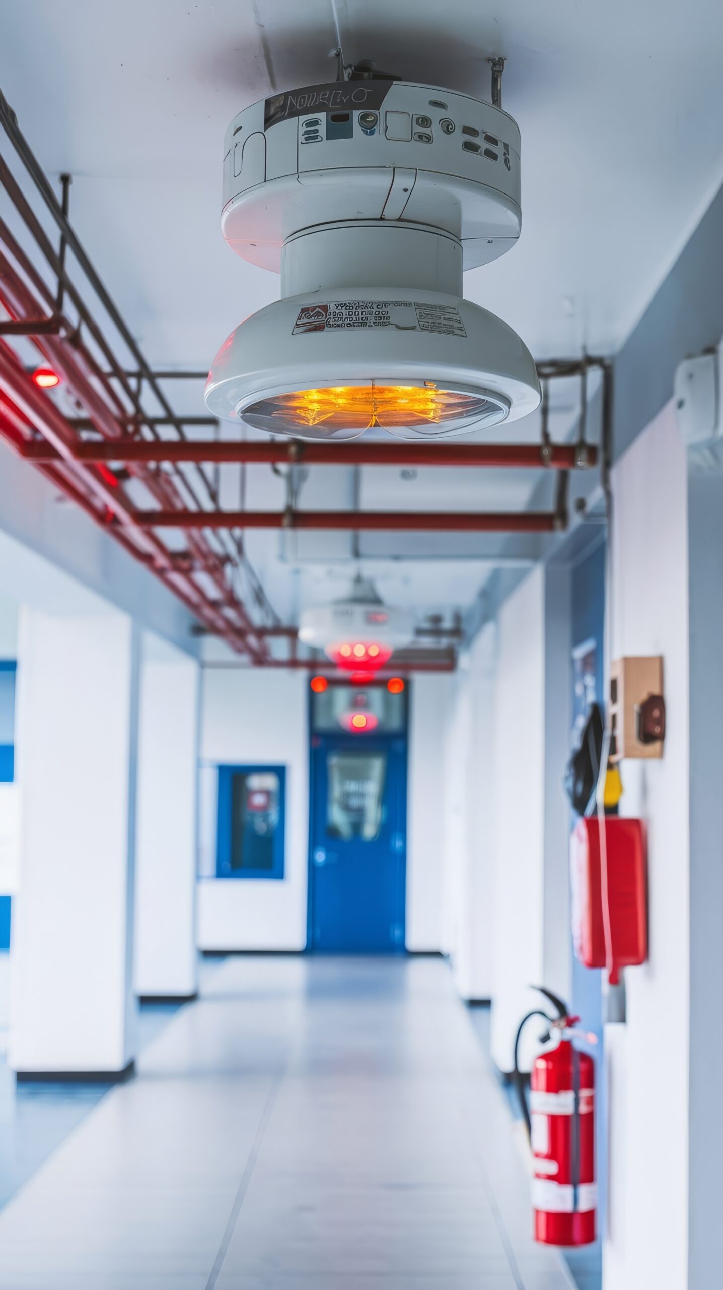
A duct smoke detector is not primarily a life-safety notification device. Its job is narrower and mechanical: sense smoke entrained in moving air inside an HVAC duct and trigger a shutdown before the air handling system can pull that smoke into other floors or fire compartments. A central air handler can move thousands of cubic feet of air per minute through shared return plenums and supply ductwork, and if a fire starts anywhere near an intake, a running fan can distribute smoke through a building far faster than the fire itself would spread. Duct detectors and the shutdown relays, fan interlocks, and smoke dampers they trigger exist to interrupt that path.
The core practical tradeoff in designing this interlock is where to put the detection and how aggressively to shut the system down. Detecting on the supply side stops contaminated air from being pushed into occupied spaces; detecting on the return side catches smoke before it reaches the air handler and mixes across zones. Codes typically require both, at different airflow thresholds, and the placement decision interacts directly with duct geometry, false-alarm risk, and how the unit is sequenced to shut down fans and close dampers without stranding a building without ventilation unnecessarily.
How Duct-Mounted Detection Works
A duct smoke detector consists of a sensing housing mounted on the exterior of the duct, connected to an inlet sampling tube and an exhaust tube that penetrate the duct wall. The inlet tube spans the width of the duct with a series of holes drilled along its length, oriented to face directly into the airflow. Differential pressure created by the moving airstream draws a small sample of duct air through the inlet tube, across the sensing chamber (typically a photoelectric, light-scattering chamber), and back out through the exhaust tube. Because the sampling relies entirely on the duct’s own airflow to move air across the sensor, the detector only functions correctly within a defined air velocity range specified by the manufacturer; it is not a standalone open-area smoke detector and is not listed for that use.
When the sensing chamber detects smoke above the alarm threshold, the detector’s relay output typically does two things: it de-energizes the fan starter circuit (or sends a shutdown command to the unit controller) and signals any associated smoke or combination fire/smoke dampers to close. Depending on the design, this relay logic can operate as a self-contained interlock independent of the building fire alarm control panel, or it can be wired as an initiating device that also reports to the panel.
Placement, Installation, and Code Requirements
In the United States, duct smoke detection requirements come primarily from two coordinated sources: NFPA 90A, Standard for the Installation of Air-Conditioning and Ventilating Systems, and the International Mechanical Code (IMC), Section 606, Smoke Detection Systems Control. The IMC requires duct smoke detectors listed and labeled to UL 268A, installed in accordance with NFPA 72. Under IMC 606.2, a smoke detector is generally required in the return air system of an air distribution system with a design capacity greater than 2,000 cfm, and systems with a return air riser serving multiple stories and a combined capacity greater than 15,000 cfm require a detector at each story, located upstream of the connection to the riser. NFPA 90A applies a parallel logic on the supply side: detectors are placed downstream of filters and ahead of branch connections to stop supply fans before contaminated air disperses into the distribution system. An exception in both documents removes the requirement where the air distribution system cannot spread smoke beyond the space where it originates, or where its sole function is exhaust to the outside.
Sampling tube geometry matters as much as the decision of where in the system to detect. NFPA 72’s installation guidance calls for duct detectors to be located at least six duct widths downstream of any bend, branch connection, or air inlet that would create turbulence, so the air sample reaching the sensing chamber is representative of the full duct cross-section rather than a stratified pocket of air. Where six duct widths is not physically achievable, the detector should be positioned as far from the disturbance as the installation allows. The inlet tube itself must run the full width of the duct with its sampling holes facing into the airflow, and detector housings are generally mounted on the side or top of the duct rather than the bottom, partly to reduce exposure to condensation. Code also requires access for inspection and maintenance, and where a detector is installed in a concealed location or more than roughly 10 feet above the finished floor without a visible indicator, a remote alarm/trouble indicator is required so responding personnel can identify an activated unit without opening ceiling or duct access panels.
Common Failure Modes and Limitations
Most duct detector problems trace back to installation geometry or environmental conditions rather than the sensor itself. A unit mounted too close to a bend or branch samples turbulent, unrepresentative air and can either miss a real smoke condition or nuisance-alarm on dust kicked up by turbulence. High humidity or condensation inside the duct, common near cooling coils, can produce false alarms or coat the sensing chamber, and manufacturers generally recommend keeping detectors away from locations prone to moisture carryover. Dust and lint accumulation in the sampling tube and chamber over time reduces sensitivity gradually, which is why sensitivity testing, not just a functional alarm test, is part of ongoing maintenance.
A frequently overlooked limitation is airflow dependency: because the detector relies on duct air velocity to pull a sample across the chamber, it cannot reliably detect smoke when the associated fan is off or operating below the minimum velocity the detector was listed and calibrated for. Variable air volume systems turning down to low flow, or units cycling off during unoccupied periods, can create windows where duct detection is not effective. Testing practice has a related pitfall: a magnet test only confirms that the detector’s internal test circuit and output relay function; it does not verify that the sampling tube is clear or that smoke can actually reach the sensing chamber. An aerosol or canned-smoke test introduced at the sampling point, with the fan running, is needed periodically to confirm the full sampling path works, not just the electronics.
Integration with the Broader Fire Alarm System
Duct detectors can be configured two ways relative to the building fire alarm system. In the simplest arrangement, the detector operates as a standalone HVAC control interlock, shutting down the fan and closing dampers through its own relay without reporting to the fire alarm control panel at all; NFPA 90A permits automatic HVAC shutdown by detectors that are not part of the building fire alarm system. In practice, most designs tie duct detectors into the fire alarm system as initiating or supervisory devices so that an activation is logged, annunciated, and visible to responding personnel and the monitoring service, and so the event can be coordinated with other fire alarm sequences such as elevator recall or smoke damper status reporting. In buildings with engineered smoke control per NFPA 92, duct detector signals may also need to coordinate with stairwell pressurization and zoned smoke exhaust sequences rather than simply shutting equipment down. For related fire alarm integration guidance, see SectechMedia’s guide to fire alarm control panels.
Commissioning Checklist
- Confirm each duct smoke detector is listed and labeled to UL 268A for duct application, matched to the duct’s actual air velocity range.
- Verify supply- and return-side placement meets the applicable airflow thresholds in NFPA 90A and IMC Section 606, including the 15,000 cfm return riser condition at each served story.
- Check that each detector housing is located at least six duct widths from bends, branch takeoffs, or inlets, or as far as physically achievable where that spacing cannot be met.
- Confirm the inlet sampling tube spans the full duct width with holes oriented into the airflow, and that the exhaust tube is unobstructed.
- Functionally test with an actual aerosol or canned-smoke test at the sampling tube with the fan running at normal operating airflow, not only a magnet or electronic test.
- Verify the fan shutdown and damper closure sequence activates correctly and within the expected time, and that any FACP annunciation or supervisory signal reports as designed.
- Confirm remote alarm/trouble indicators are installed and legible for any detector in a concealed or elevated location, and document test results for the authority having jurisdiction.