
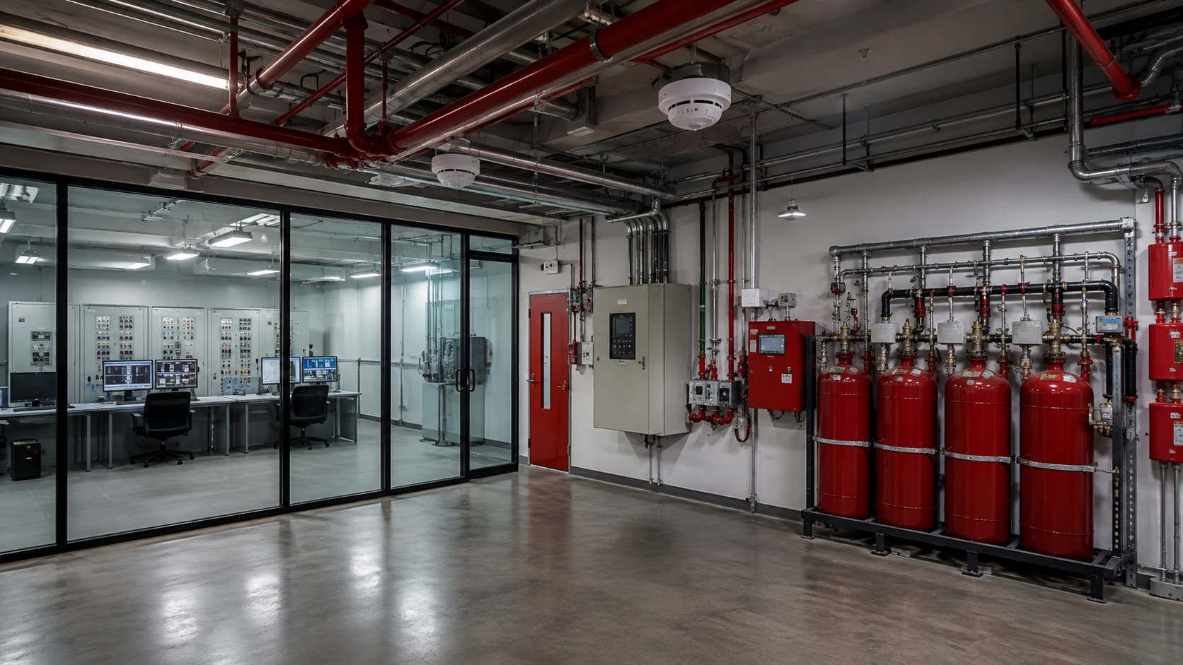
Networked fire alarm systems distribute detection, control and annunciation across panels, nodes and communication paths. Normal status does not prove that a single cable break, failed node or power loss will be isolated correctly. Fault-tolerance testing verifies that the design reports trouble promptly, preserves required alarm functions and returns to service without hidden faults.
Map the network and required survivability
Start with current drawings showing panels, loops, network interfaces, annunciators, power supplies and communication media. Identify redundant paths, isolators and dependencies on shared switches or fiber converters. The approved design and equipment documentation should define which functions must remain available under each fault.
Record normal node status, software versions, synchronization and event routing. A test cannot demonstrate recovery if the baseline already contains intermittent trouble or undocumented bypasses.
Build a controlled fault matrix
Plan one fault at a time: open circuit, short circuit where safe, loss of a network segment, loss of a node, primary power interruption and failure of a redundant path. Define the expected panel indication, affected area, notification route and restoration behavior before introducing the condition.
Coordinate impairments with responsible personnel and emergency procedures. Use approved test methods and never defeat life-safety protection without an authorized compensating measure. The purpose is to verify design behavior, not to improvise destructive testing.
Observe alarm and trouble separation
Confirm that a communication fault generates the correct trouble condition and identifies the affected segment. Then introduce a permitted alarm input on an unaffected part of the network. The alarm should retain its intended priority, location and cause-and-effect actions rather than being masked by the existing trouble.
Check local panel operation, remote annunciation, supervising-station transmission and event logging. SectechMedia’s overview of fire alarm control panels explains how field-device events depend on the wider control architecture.
Test redundancy and degraded modes
Where a ring, dual path or redundant server is provided, measure transfer behavior and identify any temporary loss of visibility. Verify that isolators limit the fault to the intended section. For IP-connected components, confirm that network failover does not introduce stale status, duplicate events or clock drift.
Test battery-backed operation and restoration in the sequence required by the manufacturer. A node that reconnects should synchronize configuration and state without creating false alarms or silently clearing unresolved trouble.
Close every impairment with evidence
Record the injected fault, timestamps, displayed messages, surviving functions, restoration sequence and corrective action. Reconcile all panels and supervising systems to normal, then verify that no disabled point or bypass remains. Repeat tests after topology changes, panel replacement or major software updates. NIST fire research resources reinforce the importance of empirical performance evidence in fire-safety engineering.
Review trends after restoration
After normal service returns, review trouble history for repeated link flaps, node resets or delayed synchronization. Intermittent patterns can reveal marginal cabling, unstable power or overloaded interfaces that a single pass/fail test misses. Assign follow-up monitoring and confirm that maintenance records identify the exact topology and firmware state tested.
Leave a Reply