Tag: fire detection

  • Fire Alarm Network Fault-Tolerance and Recovery Testing

    Fire Alarm Network Fault-Tolerance and Recovery Testing

    Networked fire alarm systems distribute detection, control and annunciation across panels, nodes and communication paths. Normal status does not prove that a single cable break, failed node or power loss will be isolated correctly. Fault-tolerance testing verifies that the design reports trouble promptly, preserves required alarm functions and returns to service without hidden faults.

    Map the network and required survivability

    Start with current drawings showing panels, loops, network interfaces, annunciators, power supplies and communication media. Identify redundant paths, isolators and dependencies on shared switches or fiber converters. The approved design and equipment documentation should define which functions must remain available under each fault.

    Record normal node status, software versions, synchronization and event routing. A test cannot demonstrate recovery if the baseline already contains intermittent trouble or undocumented bypasses.

    Build a controlled fault matrix

    Plan one fault at a time: open circuit, short circuit where safe, loss of a network segment, loss of a node, primary power interruption and failure of a redundant path. Define the expected panel indication, affected area, notification route and restoration behavior before introducing the condition.

    Coordinate impairments with responsible personnel and emergency procedures. Use approved test methods and never defeat life-safety protection without an authorized compensating measure. The purpose is to verify design behavior, not to improvise destructive testing.

    Observe alarm and trouble separation

    Confirm that a communication fault generates the correct trouble condition and identifies the affected segment. Then introduce a permitted alarm input on an unaffected part of the network. The alarm should retain its intended priority, location and cause-and-effect actions rather than being masked by the existing trouble.

    Check local panel operation, remote annunciation, supervising-station transmission and event logging. SectechMedia’s overview of fire alarm control panels explains how field-device events depend on the wider control architecture.

    Test redundancy and degraded modes

    Where a ring, dual path or redundant server is provided, measure transfer behavior and identify any temporary loss of visibility. Verify that isolators limit the fault to the intended section. For IP-connected components, confirm that network failover does not introduce stale status, duplicate events or clock drift.

    Test battery-backed operation and restoration in the sequence required by the manufacturer. A node that reconnects should synchronize configuration and state without creating false alarms or silently clearing unresolved trouble.

    Close every impairment with evidence

    Record the injected fault, timestamps, displayed messages, surviving functions, restoration sequence and corrective action. Reconcile all panels and supervising systems to normal, then verify that no disabled point or bypass remains. Repeat tests after topology changes, panel replacement or major software updates. NIST fire research resources reinforce the importance of empirical performance evidence in fire-safety engineering.

    Review trends after restoration

    After normal service returns, review trouble history for repeated link flaps, node resets or delayed synchronization. Intermittent patterns can reveal marginal cabling, unstable power or overloaded interfaces that a single pass/fail test misses. Assign follow-up monitoring and confirm that maintenance records identify the exact topology and firmware state tested.
    Reference sources

  • Flame Detector Field-of-View and Obstruction Audit

    Flame Detector Field-of-View and Obstruction Audit

    Optical flame detectors depend on a clear relationship between the hazard and the sensor. A detector may remain powered, supervised and free of trouble signals while its effective field of view has been reduced by new equipment, temporary storage, pipework, dirt or a changed process layout. A field-of-view audit checks whether the installed detection geometry still matches the current hazard.

    Reconstruct the detection objective

    Identify the fuels, likely flame locations, release scenarios, required response and environmental constraints that informed the original design. Review detector technology, listed viewing angle, sensitivity setting, mounting height and orientation using the manufacturer’s current documentation. Do not substitute a generic cone on a drawing for model-specific coverage data.

    Define the protected hazard volume rather than checking only whether the detector points toward the room. Pools, spray releases, elevated equipment and shielded process areas can require different sightlines.

    Survey physical and process changes

    Walk each detector’s view from both the sensor and hazard perspectives. Record fixed obstructions, movable equipment, cable trays, structural steel, ventilation components and transparent barriers. Examine whether maintenance platforms, stored materials or seasonal equipment can enter the sightline after the audit.

    Process changes matter as much as construction. A vessel, burner or transfer point may have moved while the detector remained in its original position. Update drawings and photographs so the next inspection can distinguish gradual drift from an approved design change.

    Check environmental interference

    Inspect lenses, windows and protective housings for contamination, condensation, coating damage or cleaning residue. Review sources of radiation and interference relevant to the detector technology, including hot equipment, welding, direct sunlight and reflections. Environmental mitigation should follow the manufacturer’s instructions and the approved fire-protection design.

    NFPA 72 establishes requirements for fire alarm and signaling systems, but acceptance and maintenance still depend on listed equipment instructions and site-specific engineering. The audit should therefore connect code obligations to the actual detector model and hazard.

    Use controlled functional testing

    Where permitted, use an approved test source and follow the manufacturer’s distance, alignment and safety requirements. Confirm alarm receipt, correct device identity, cause-and-effect actions and reset behavior. A test that activates the detector from an easy position does not prove coverage of the intended hazard; test points should represent the risk geometry.

    Coordinate with operations and impairment procedures before testing. SectechMedia’s overview of fire alarm control panels explains how field-device events enter the wider alarm and response chain.

    Document gaps and corrective action

    Classify findings as obstruction, orientation, contamination, changed hazard, configuration or documentation issues. Assign owners and completion dates, then re-test corrected positions. Retain annotated photographs, detector settings and test evidence. The goal is to demonstrate continuing coverage, not merely to show that a detector generated one alarm during an annual visit.

    Reference sources

  • Smoke Detector Sensitivity Testing and Contamination Maintenance

    Smoke Detector Sensitivity Testing and Contamination Maintenance

    A smoke detector can remain connected and report normal communications while its sensing chamber becomes contaminated or its response drifts. Maintenance must therefore look beyond panel connectivity. Sensitivity testing, device diagnostics and environmental history provide evidence that a detector remains within its approved operating range.

    Understand what the system reports

    Addressable detectors may provide a sensitivity value, contamination level or maintenance alert. The meaning of those values is manufacturer-specific and must be interpreted with the approved documentation. A percentage or bar graph should not be converted into a pass decision without knowing the reference range and compensation method.

    Some devices automatically compensate for gradual contamination. Compensation can preserve performance for a period, but it is not unlimited and should not be treated as a substitute for cleaning or replacement. Record when the device approaches a maintenance threshold and whether the panel reports that state to operators.

    Test within an approved maintenance program

    Use methods permitted by the applicable code, authority and manufacturer. Functional aerosol testing confirms that smoke can enter the chamber and generate an alarm, while sensitivity testing evaluates the response threshold. Those are related but different questions, so one result should not be used to claim that both were tested.

    Coordinate impairment controls before testing. Notify monitoring parties, protect occupants and restore all disabled outputs after the work. The record should identify the detector, location, method, result, tester, equipment and any corrective action.

    Investigate the environmental cause

    Repeated contamination may indicate dust, construction activity, steam, aerosols, insects or unsuitable air movement. Cleaning the detector without addressing the environment can produce a cycle of nuisance alarms and early failure. Compare maintenance history across nearby devices to identify a local pattern.

    Confirm that detector type and placement remain suitable after room-use changes. A space converted into a workshop, kitchen or high-airflow area may need a design review rather than repeated adjustment. Settings should not be widened simply to silence alarms unless the change is engineered, approved and documented.

    Use trends to plan replacement

    Track devices that repeatedly approach contamination limits, fail sensitivity checks or require frequent cleaning. Trending supports risk-based replacement and helps identify batches exposed to similar conditions. It also distinguishes a single defective device from a broader environmental or design problem.

    Close maintenance by verifying normal panel state, remote annunciation, monitoring communication and updated records. Smoke-detector assurance supports the wider Fire & Safety program by proving that connected devices remain capable of performing their detection function, not merely responding on the network.

    Maintenance analytics should support, not replace, required inspection and testing. Assign responsibility for reviewing contamination trends and overdue work orders, and ensure technicians can trace every device result to its physical location. Any detector removed for service should remain controlled so that an untested device is not returned to the wrong address.

    Reference sources

  • Comelit-PAC Launches Linear Beam Smoke Detector Range for Warehouses and Large Open Spaces

    Comelit-PAC Launches Linear Beam Smoke Detector Range for Warehouses and Large Open Spaces

    Comelit-PAC has launched a new range of linear beam smoke detectors designed for warehouses, atriums, industrial facilities, sports halls and other high-ceiling environments, the company said on August 26, 2026. The detectors use reflective infrared beam technology to monitor for smoke over distances of up to 120 meters, and the range comprises four models split between addressable and conventional variants covering 5 to 60 meters and 50 to 120 meters respectively.

    The addressable models are compatible with Comelit-PAC’s Logifire panels, while conventional variants work with standard fire alarm control panels; all models are certified to EN54-12, and the addressable versions add EN54-17 certified short-circuit isolation. The detectors include smart alignment technology that automatically optimizes signal strength during commissioning, an integrated laser pointer to assist installation, and automatic compensation for environmental drift such as dust buildup, minor structural movement and temperature fluctuation, with maintenance alerts generated when servicing is needed. “As warehouses become larger, industrial facilities more complex and public spaces increasingly multi-purpose, there’s growing demand for technologies to deliver reliable coverage without adding unnecessary complexity,” said Mandy Bowden, Fire Systems Business Manager UK & ROI at Comelit-PAC.

    Beam smoke detection is a standard approach for protecting large-volume spaces where point smoke detectors would be impractical to install and maintain in sufficient density, and reducing false alarms from environmental drift has been a persistent integrator complaint with older beam detector generations. The addressable range’s real-time alignment display and dual day/night sensitivity settings target that maintenance burden directly, a common driver of beam detector replacement cycles in large commercial and industrial buildings.

  • Fire Detection Systems: Smoke, Heat, Flame and Gas Detection Explained

    Fire Detection Systems: Smoke, Heat, Flame and Gas Detection Explained

    Fire detection is a layered engineering discipline. No single detector is ideal for every environment because fires develop differently depending on fuel, ventilation, ceiling height, temperature and process conditions. Modern systems therefore use combinations of smoke, heat, flame and gas detection selected around the risk.

    Smoke detectors are common in buildings because many fires produce aerosols before dangerous heat develops. Optical detectors are widely used, while aspirating smoke detection can provide very early warning in data centers, clean rooms and high-value facilities.

    Heat detectors respond to fixed temperature thresholds or rapid temperature rise. They are useful where smoke detection would create nuisance alarms, such as dusty or steamy environments, but generally respond later than sensitive smoke systems.

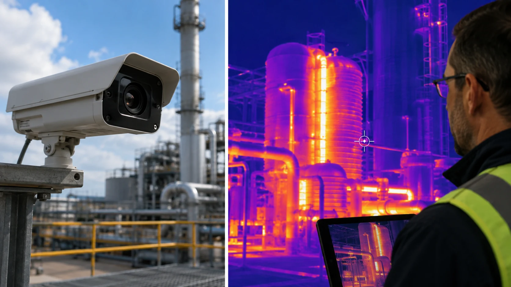
    Flame detectors identify optical signatures from combustion. Ultraviolet, infrared and multispectrum designs can react rapidly to open flames and are common in refineries, fuel storage, aircraft hangars and process facilities.

    Gas detection addresses combustible, toxic or fire-related gases. In some industrial risks, gas monitoring can identify a dangerous release before ignition occurs. Carbon monoxide sensing may also provide useful fire information in selected applications.

    Detector selection must consider false-alarm sources, coverage geometry, maintenance and the consequences of delayed detection. Integration with alarms, suppression, smoke control, shutdown systems and emergency communications is equally important.

    The best fire-detection design is therefore hazard-based. Engineers should ask what is likely to happen first in a credible fire scenario—smoke, heat, flame or gas—and choose technologies that detect that stage reliably while remaining practical to maintain.