Category: Fire & Safety

  • Waco Fire Department to Pilot Qwake C-THRU Thermal-Imaging AR Helmets in $396K Deal

    Waco Fire Department to Pilot Qwake C-THRU Thermal-Imaging AR Helmets in $396K Deal

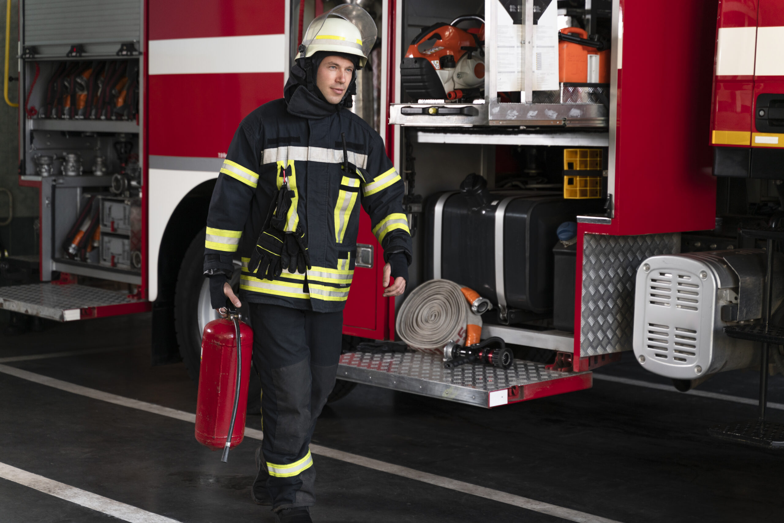
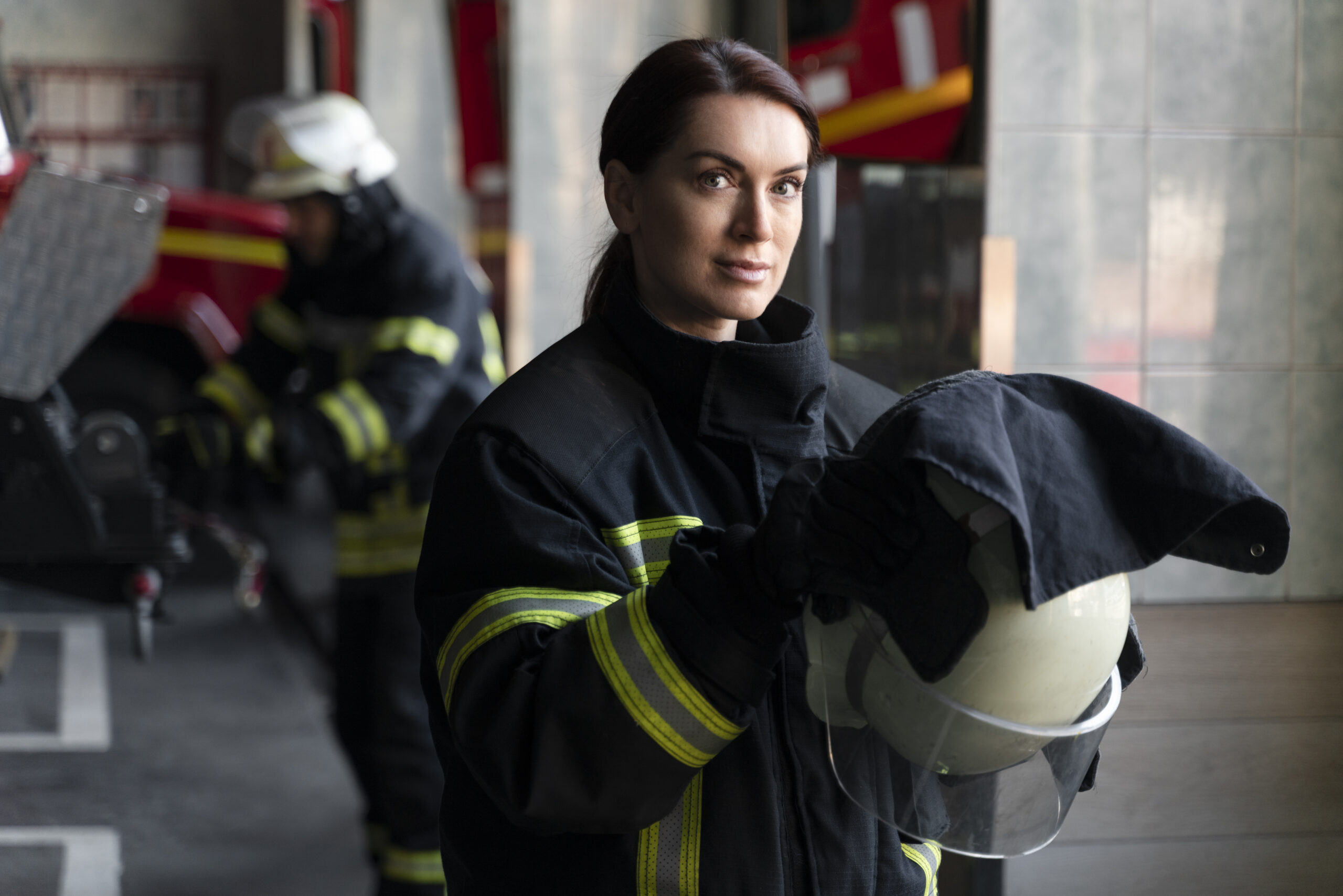
    The Waco, Texas, City Council has approved a three-year, $396,000 agreement with Austin-based Qwake Technologies Inc. to supply the Waco Fire Department with 16 helmet-mounted C-THRU thermal-imaging and augmented-reality units, according to the Waco Tribune-Herald and Firehouse.com. The council action, reported September 28, 2026, makes Waco the second fire department in Texas to field-evaluate the hardware.

    What the Agreement Covers

    The deal provides for purchase and support of the 16 C-THRU helmet-mounted devices along with command-center software, firefighter training, connectivity services and related accessories such as cases, mounts and command tablets. The city negotiated a 30% discount on the augmented-reality systems and a 60% discount on accessories compared with retail pricing, obtained through a sole-source procurement process, according to the Tribune-Herald report.

    How the System Works

    Qwake’s C-THRU platform combines thermal imaging with a heads-up augmented-reality display, using the company’s Edge Detection technology to help firefighters see through smoke and navigate structures hands-free. Qwake designers will train Waco firefighters before the units enter active service, which city officials expect to begin next year.

    The pilot reflects a broader push among Texas municipal fire departments to evaluate wearable situational-awareness technology, though wider adoption will depend on how the equipment performs in live fireground conditions during the evaluation period. More fire and life safety developments are tracked in the SectechMedia Technology News archive.

    Sources

  • Pye-Barker Fire & Safety Acquires Union AlarmTronic, Expanding Security Alarm Footprint in New Jersey

    Pye-Barker Fire & Safety Acquires Union AlarmTronic, Expanding Security Alarm Footprint in New Jersey

    Pye-Barker Fire & Safety, which bills itself as the largest fully integrated fire protection, life safety and security services provider in the United States, announced on September 29, 2026, that it has acquired Union AlarmTronic, LLC, a security alarm company based in Springfield, New Jersey. The deal deepens Pye-Barker’s operational footprint in the state, adding local service capacity and technical expertise to its existing Northeast operations.

    According to the company’s press release, Union AlarmTronic was founded in 1989 and has completed more than 20,000 security installations across New Jersey, providing access control, video surveillance, intercom, integrated security and traditional alarm monitoring services. The company is led by owner Fred Rosenfeld, who entered the security business through his father Len Rosenfeld’s family operation.

    “We have proudly protected people and property and provided high-caliber service to customers in New Jersey for decades,” Rosenfeld said in the announcement. “With Pye-Barker, we will continue our commitment to install and maintain security systems that protect customers while being able to offer expanded full-service fire protection.”

    Pye-Barker Fire & Safety CEO Bart Proctor framed the deal as both a talent and capability acquisition. “When we met with team members at Union AlarmTronic, their passion for customers and their community stood out,” Proctor said. “Incorporating their expertise, service and team approach into the Pye-Barker family enables us to protect even more people in the state.”

    Per the release, Union AlarmTronic’s trained technicians will remain in place to continue serving existing New Jersey customers under the Pye-Barker umbrella, a common integration approach the company has used across its string of regional acquisitions. Nelson Mullins Riley & Scarborough, LLP represented Pye-Barker in the transaction, while Mesirow Investment Banking served as exclusive financial advisor to Union AlarmTronic. Financial terms were not disclosed.

    Part of a broader consolidation push

    The Union AlarmTronic deal is the latest in a long run of regional roll-ups for Pye-Barker, which has been aggressively acquiring independent fire-protection, suppression and security-alarm companies across the country throughout 2025 and 2026 — including recent deals for Suppression Systems, Inc. in the Pacific Northwest and FSD Protection in Texas. The strategy mirrors a wider wave of consolidation across the physical security and fire-safety services sector, where private-equity-backed platforms and large integrated providers are absorbing independent regional operators to broaden geographic coverage and cross-sell fire, life-safety and security-alarm services to the same commercial customer base.

    For end users in New Jersey, the acquisition means Union AlarmTronic’s existing access control, video surveillance and alarm monitoring customers gain access to Pye-Barker’s broader fire-protection and life-safety service lines, while the local technician base and customer relationships are expected to remain intact through the transition.

    Source: Pye-Barker Fire & Safety press release, PR Newswire, September 29, 2026. Confidence rating: DIRECT (primary company press release with named executive quotes).

    Sources and Further Reading

  • FSRI Report Examines Systems Behind 2025 Southern California Fire Losses

    FSRI Report Examines Systems Behind 2025 Southern California Fire Losses

    The Fire Safety Research Institute (FSRI) has released a systems-level analysis of the January 2025 Palisades and Eaton fires in Southern California. Commissioned after the disaster, the report examines how preparedness, infrastructure, evacuation, emergency operations and the built environment interacted during fast-moving community conflagrations.

    Analysis identifies interconnected pressures

    FSRI’s report contains 175 findings and 266 recommendations. Its evidence base includes technical discussions with responders and subject-matter experts, resident interviews and surveys, site assessments, geospatial analysis, radio communications, dispatch records and vehicle-location data.

    The institute says the outcomes were shaped by the combined performance of multiple systems rather than one point of failure. Areas examined include emergency management, water and electric utilities, weather and vegetation, evacuation warnings, transportation, fire and law-enforcement operations, fatalities and building conditions.

    Recommendations extend beyond one incident

    The recommendations address community-scale wildfire mitigation, readiness for wind-driven conflagrations, situational awareness, infrastructure resilience, evacuation coordination, interoperable communications, wildfire-resistant construction, suppression strategy and post-suppression monitoring. That systems approach matters because extreme fire conditions can exceed assumptions built into otherwise well-established preparedness programs.

    For public-safety and critical-infrastructure teams, the report provides a structured basis for reviewing dependencies between warning systems, communications, utilities and field operations. SectechMedia’s fire and safety coverage tracks technologies and operational practices used to improve detection, response and resilience.

    Sources

  • Fire Alarm Secondary Power: Battery Sizing, Load Testing and Transfer Verification

    Fire Alarm Secondary Power: Battery Sizing, Load Testing and Transfer Verification

    Fire alarm secondary power is a designed operating system, not simply a pair of batteries in a cabinet. Capacity calculations, charger performance, connected loads, battery condition and automatic transfer all contribute to whether the system can continue operating when primary power is lost.

    This guide complements the practical material in Articles & Analysis and the Fire Safety archive.

    Establish the documented load

    Start with the approved equipment list and identify standby and alarm current for the control unit, annunciators, communication equipment, modules, detectors, notification power supplies and other loads served by the same batteries. Field additions can invalidate an older calculation even when the panel shows no trouble.

    Required standby and alarm periods, design margins and derating factors depend on the adopted code edition, system type, project documents, listed equipment and authority having jurisdiction. One duration or percentage should not be treated as universal.

    Inspect installation and condition

    Record battery manufacturer, model, rated capacity, installation date and terminal arrangement. Look for swelling, leakage, corrosion, loose connections, damaged insulation, excessive heat and cabinet contamination. Confirm polarity and secure mounting. Open-circuit voltage alone does not demonstrate usable capacity under load.

    Verify charger and supervision

    Measure charger and battery conditions using the listed equipment procedure and approved test method. Confirm that battery disconnection produces the intended supervised trouble and that restoring the circuit clears correctly. Investigate a charger that masks a weak battery during normal mains operation.

    Test transfer from primary power

    Use the authorized procedure to remove primary power and observe automatic transfer. The panel, communication path and required connected functions should remain stable while the correct trouble signal appears locally and remotely. Restore primary power and verify recharge indication and normal status. Coordinate the test to prevent an unintended dispatch.

    Apply an appropriate load test

    Testing may use the system load, a listed battery tester or another approved method. Record initial conditions, applied load, duration, measured values and recovery. A result outside the manufacturer’s limits or project criteria requires evaluation and corrective action. Replacing batteries without investigating excessive load or charger faults may only postpone another failure.

    Keep calculations aligned with the field

    • Update current totals after adding devices, modules or communicators.
    • Include auxiliary power supplies and their own batteries in the inventory.
    • Link battery records to the exact panel and cabinet.
    • Document replacement, disposal and post-work retesting.

    Acceptance should combine calculation review, physical inspection, supervision, transfer behavior and load evidence. The final report should cite the applicable requirements and preserve enough detail for the next technician to repeat the method.

    Sources

  • Fire Door and Access Control Interface Testing: Fail-Safe Release Without Security Gaps

    Fire Door and Access Control Interface Testing: Fail-Safe Release Without Security Gaps

    Fire alarm and access control systems often share control of doors, but they serve different objectives. Emergency operation must support safe egress and required fire or smoke separation while normal operation protects controlled areas. A correct interface test proves the approved sequence instead of assuming that every lock should simply release.

    Related commissioning guidance appears in Articles & Analysis and the Fire Safety archive.

    Start with the approved door schedule

    For each opening, identify the door and frame rating, locking hardware, closer, hold-open device, request-to-exit equipment, emergency release, power source and control modules. Record which alarm zone or building condition should affect it. Required behavior depends on the door function, adopted codes, listed hardware, approved design and authority having jurisdiction; not every controlled door universally fails open.

    Trace the interface path

    Determine whether the fire alarm provides a dry contact, supervised module or networked command, and which access-control component removes or changes power. Verify fault supervision where required. Labeling should allow a technician to connect the fire panel point to the exact door and access output without relying on institutional memory.

    Test normal emergency operation

    Initiate the approved fire-alarm condition and observe the complete sequence. Confirm that affected locks, holders and operators reach their specified state; that occupants can egress as designed; and that fire or smoke doors close and latch where required. Test local manual-release devices independently. A successful access-control software command does not prove the hardwired emergency path.

    Test loss of power and communication

    Simulate the power-loss conditions included in the design, including local access supply, fire-alarm interface supply and network communication where applicable. Observe whether backup power changes the sequence. Verify trouble indications and confirm that a single fault does not silently leave a door in an unsafe or permanently unsecured condition.

    Verify reset and relocking

    After the initiating condition clears, reset systems in the documented order. Confirm that doors do not relock while an emergency release remains active, and that authorized relocking restores security without preventing required egress. Check door alignment, latch engagement and position monitoring; an electrical reset cannot compensate for damaged hardware.

    Use a door-by-door record

    • Opening identifier and physical location
    • Normal, alarm, power-loss and manual-release states
    • Panel, access controller and monitoring messages
    • Release, closure, latching and reset observations
    • Defect owner, corrective action and retest result

    Coordinate testing with fire-safety, security and facilities teams. Acceptance criteria and periodic intervals should be taken from the adopted requirements and project documentation rather than generalized across every occupancy.

    Sources

  • Sprinkler Supervisory Monitoring: Valves, Waterflow and Fire Pump Signals

    Sprinkler Supervisory Monitoring: Valves, Waterflow and Fire Pump Signals

    A sprinkler system is not fully supervised merely because a fire alarm panel displays a normal condition. Valves, waterflow devices, pressure switches, pumps, power supplies and communication paths must report the right condition with a label that operators can act on.

    Commissioning should trace each field input through the panel, remote monitoring and restoration process. Related technical material is available in Articles & Analysis and the Fire Safety archive.

    Keep signal classes distinct

    An alarm signal indicates a condition associated with fire response, such as sustained waterflow. A supervisory signal indicates an off-normal condition in a fire-protection system, such as a control valve moving from its intended position. Trouble identifies a fault affecting monitoring or operation. The precise classification and timing must follow adopted requirements, approved design documents, listed devices and the authority having jurisdiction.

    Verify valve supervision

    Identify every supervised valve and confirm its normal position. Operate the valve slowly and verify that the correct point appears locally and at the monitoring destination. The displayed label should identify the actual system and location, not a generic input number. Restore the valve fully and confirm that the supervisory condition clears without leaving the system impaired.

    Test waterflow as an end-to-end event

    Use the approved test connection or procedure and record the sequence from water movement to panel indication, notification and remote receipt. Mechanical retard features and programmed delays should be evaluated against the approved design. Reset the system, check for leakage and verify that the alarm does not remain latched unnoticed.

    Include pressure and fire-pump information

    Where monitored, test pressure-related inputs, pump running, controller trouble, power conditions and other specified states. Do not infer pump performance from a status contact; hydraulic and controller tests are separate activities. Confirm that operators understand which signal requires emergency response and which requires maintenance investigation.

    Coordinate testing safely

    • Notify the monitoring center and affected occupants before testing.
    • Use impairment procedures when valves or pumps are taken out of normal service.
    • Protect against unintended water discharge and equipment damage.
    • Restore every bypass, valve and notification function after the test.

    Build a defensible record

    Document device type, address, physical location, normal state, activation method, panel text, remote text, timestamps and restoration. Testing intervals and acceptance details vary by jurisdiction and system type, so the record should cite the applicable procedure rather than asserting one universal schedule. Unresolved mismatches should remain visible until corrected and retested.

    Sources

  • Fire Detection in High-Ceiling Spaces: Smoke Stratification, Beam Detection and Aspirating Sampling

    Fire Detection in High-Ceiling Spaces: Smoke Stratification, Beam Detection and Aspirating Sampling

    High-ceiling spaces challenge the assumption that smoke will quickly reach a detector mounted at the highest point. Warehouses, atria, aircraft hangars and production buildings can delay or redirect smoke through temperature gradients, ventilation and large internal volumes.

    The design question is therefore not simply which detector has the longest range. Engineers must identify the fire signatures, airflow and response objective, then select and validate a detection method. More guidance is available in Articles & Analysis and the Fire Safety archive.

    Understand smoke movement first

    Buoyant smoke can cool as it rises and may stabilize below the roof, a condition commonly described as stratification. Heating, roof temperature, air handling, racking and stored goods can change the plume. A design based only on clear ceiling height may miss these interactions.

    Compare available detection approaches

    Point smoke detectors are familiar and provide individual device locations, but response can be delayed when smoke takes time to reach the ceiling. Optical beam detectors monitor obscuration across a long path and can cover broad open areas, although alignment, structural movement and obstructions require attention. Aspirating smoke detection draws air through a pipe network to a central detector and can sample at selected heights, but pipe transport time, airflow balance, contamination and maintenance access must be engineered.

    Account for the operating environment

    • Map normal and emergency ventilation modes.
    • Review roof geometry, cranes, banners, racks and future storage changes.
    • Consider dust, condensation, sunlight and temperature variation.
    • Provide access for alignment, sampling-hole inspection and detector service.

    Use performance-based evidence where needed

    NFPA research on high-ceiling detector spacing shows why ceiling height deserves specific evaluation. Computational analysis, smoke tests or other approved engineering methods may be needed for unusual spaces. Spacing and acceptance criteria depend on the adopted codes, project documents, listed device instructions and the authority having jurisdiction; a single universal distance is not appropriate.

    Commission the complete signal path

    Testing should demonstrate that the selected fire signature reaches the sensing path and produces the intended alarm at the correct panel location. For beam systems, verify alignment, obscuration response and trouble conditions. For aspirating systems, check airflow supervision, pipe integrity, transport behavior and each sample point. Confirm interfaces to notification, smoke control and monitoring without assuming that one detector test proves every sequence.

    Preserve a repeatable baseline

    Document detector locations, beam paths, pipe calculations, airflow measurements, alarm thresholds, test material, environmental conditions and response times. Reassess the design when occupancy, racking, ventilation or ceiling obstructions change. A repeatable baseline makes later maintenance more useful than a simple pass label.

    Sources

  • Voice Evacuation Intelligibility Testing: From Audibility to STI

    Voice Evacuation Intelligibility Testing: From Audibility to STI

    A voice evacuation system can be loud enough to hear and still fail to deliver an understandable instruction. Audibility confirms that a signal rises above the environment; intelligibility asks whether listeners can correctly understand the words. Commissioning must address both outcomes.

    This distinction is especially important in transport halls, factories, atria, tunnels and other spaces with reverberation or changing background noise. Related fire-safety guides are available in Articles & Analysis and the Fire Safety archive.

    Begin with the design objective

    Identify the occupied zones, expected ambient conditions, message languages and emergency actions. Review speaker layout, amplifier loading, zoning, survivability and message priority. Acceptance criteria must come from the adopted codes, approved design documents, listed equipment and the authority having jurisdiction; one score should not be presented as universal.

    Separate level from clarity

    Measure the emergency message against representative background noise, but do not stop after confirming sound pressure. Excessive level can worsen reflections or distortion. Inspect speaker aiming and spacing, competing announcements, reverberant finishes and obstructions. A quiet test after hours may not represent an occupied building.

    Use STI or STIPA carefully

    Speech Transmission Index methods, including STIPA, estimate how the transmission path preserves modulations important to speech. The test signal, meter settings, measurement positions and background-noise conditions must follow the selected method and project procedure. Record the measured value with its location and operating condition rather than reporting an unexplained site average.

    Plan representative measurement points

    • Include zone boundaries, corners, areas below balconies and locations between speakers.
    • Test near machinery, ventilation outlets and other recurring noise sources.
    • Verify each message path, emergency microphone and automatic message sequence.
    • Check fault monitoring and backup-power operation separately from acoustic performance.

    Diagnose a failed area systematically

    A poor result may come from reverberation, low signal-to-noise ratio, overlapping speaker arrivals, distortion, incorrect equalization or an unsuitable speaker pattern. Corrective action might involve changing aiming, spacing, level balance, delay, acoustic treatment or the message itself. Short, direct wording often performs better than a complex sentence, but message changes require approval.

    Document and retest

    Record the instrument, calibration, test signal, floor plan position, ambient condition, system mode, measured level and intelligibility result. Link every defect to corrective work and repeat the same measurement after changes. Periodic tests should use a controlled baseline so that a genuine deterioration is distinguishable from a different test setup.

    Sources

  • NIOSH Report Details Toxic Exposure During Electric-Vehicle Battery Fire

    NIOSH Report Details Toxic Exposure During Electric-Vehicle Battery Fire

    A new National Institute for Occupational Safety and Health investigation examines an electric-vehicle fire in California where firefighters experienced symptoms after exposure to smoke and vapors from a lithium-ion battery thermal-runaway event. The report reconstructs the response and identifies lessons for respiratory protection, hazard control and post-incident monitoring.

    Battery events can remain hazardous after visible flames

    The incident involved an electric vehicle whose battery continued to produce heat and toxic products as cells failed. NIOSH’s analysis highlights the need to treat the atmosphere around a damaged high-voltage battery as potentially hazardous throughout suppression, overhaul, towing and storage. A decline in visible fire does not by itself establish that respiratory risk has ended.

    Fire departments also need clear coordination with towing operators, hazardous-material teams and medical personnel. The handoff should document battery condition, isolation distances, re-ignition indicators and exposure concerns for everyone who may approach the vehicle later.

    Respiratory protection needs objective release criteria

    Departments should maintain self-contained breathing apparatus until monitoring and incident conditions support a documented transition. Training should cover thermal runaway, decontamination, symptom reporting and delayed medical evaluation. SectechMedia tracks related systems and operational controls in its fire and life-safety coverage.

    Sources

  • Fire Alarm Notification Circuit Load and Voltage-Drop Testing

    Fire Alarm Notification Circuit Load and Voltage-Drop Testing

    A notification appliance circuit can appear healthy at the panel yet deliver insufficient voltage at its farthest device during alarm. Commissioning should verify the installed load, conductor path, synchronization and power-source behavior under realistic worst-case conditions.

    Establish the design baseline

    Record the circuit class, conductor size, route length, appliance model, candela or sounder settings and power-supply rating. Compare the installed device count with the approved calculation. Field changes can increase current without appearing in the original drawing.

    Identify boosters, isolators, end-of-line components and any shared pathways. The test plan should state which output pattern will create the highest load and which environmental or battery assumptions apply.

    Measure at the critical point

    Place the system in alarm and measure voltage at the supply and at the electrically farthest notification appliance. Test the actual programmed pattern, including synchronized strobes and temporal sounders. Confirm that each device remains within its listed operating range.

    A no-load continuity measurement is not a substitute for an alarm-state test. Loose terminals, undersized conductors and unexpected splices may only become visible when current increases.

    Include secondary power and synchronization

    Repeat required checks with the system operating from secondary power under the conditions defined by the design and applicable code. Observe whether boosters transfer correctly and whether strobes remain synchronized across power-supply boundaries.

    Where multiple circuits serve one visible area, verify that timing differences do not create confusing patterns. Confirm audibility and visibility separately; acceptable circuit voltage does not prove that the notification objective is met in the occupied space.

    Document defects and retest

    Record panel voltage, end-device voltage, current, appliance settings, battery condition and test time. Link each measurement to a circuit identifier and drawing revision. Corrective actions may include repairing connections, redistributing loads or installing an approved power supply.

    Retest after adding appliances, changing settings, replacing batteries or altering circuit routing. Integrate the results with wider Fire Detection & Automatic Fire Protection maintenance records so future technicians can compare performance rather than relying on a simple pass label.

    Use measurements for lifecycle maintenance

    Trend end-of-line voltage and alarm current across recurring tests. Gradual movement can reveal battery degradation, added appliances or deteriorating connections before a circuit reaches its operating limit. Store readings with the panel configuration and approved drawing revision.

    After corrective work, repeat the worst-case alarm pattern from normal and secondary power. Verify that trouble signals clear normally and that no device remains disabled or bypassed. Maintenance evidence should identify the instrument, calibration status and technician so measurements remain comparable.

    Include representative ambient conditions and occupied-area constraints in the record. Review open deficiencies with the responsible fire-alarm designer or service organization, assign a due date and confirm closure through a witnessed retest rather than an administrative note alone.

    Reference sources