
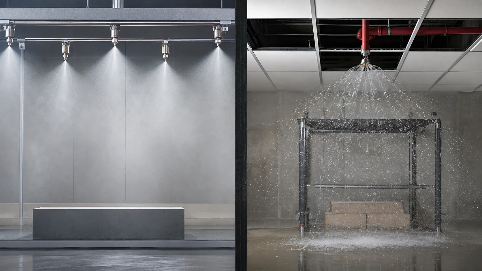
A sprinkler system is not fully supervised merely because a fire alarm panel displays a normal condition. Valves, waterflow devices, pressure switches, pumps, power supplies and communication paths must report the right condition with a label that operators can act on.
Commissioning should trace each field input through the panel, remote monitoring and restoration process. Related technical material is available in Articles & Analysis and the Fire Safety archive.
Keep signal classes distinct
An alarm signal indicates a condition associated with fire response, such as sustained waterflow. A supervisory signal indicates an off-normal condition in a fire-protection system, such as a control valve moving from its intended position. Trouble identifies a fault affecting monitoring or operation. The precise classification and timing must follow adopted requirements, approved design documents, listed devices and the authority having jurisdiction.
Verify valve supervision
Identify every supervised valve and confirm its normal position. Operate the valve slowly and verify that the correct point appears locally and at the monitoring destination. The displayed label should identify the actual system and location, not a generic input number. Restore the valve fully and confirm that the supervisory condition clears without leaving the system impaired.
Test waterflow as an end-to-end event
Use the approved test connection or procedure and record the sequence from water movement to panel indication, notification and remote receipt. Mechanical retard features and programmed delays should be evaluated against the approved design. Reset the system, check for leakage and verify that the alarm does not remain latched unnoticed.
Include pressure and fire-pump information
Where monitored, test pressure-related inputs, pump running, controller trouble, power conditions and other specified states. Do not infer pump performance from a status contact; hydraulic and controller tests are separate activities. Confirm that operators understand which signal requires emergency response and which requires maintenance investigation.
Coordinate testing safely
- Notify the monitoring center and affected occupants before testing.
- Use impairment procedures when valves or pumps are taken out of normal service.
- Protect against unintended water discharge and equipment damage.
- Restore every bypass, valve and notification function after the test.
Build a defensible record
Document device type, address, physical location, normal state, activation method, panel text, remote text, timestamps and restoration. Testing intervals and acceptance details vary by jurisdiction and system type, so the record should cite the applicable procedure rather than asserting one universal schedule. Unresolved mismatches should remain visible until corrected and retested.
Leave a Reply