Category: Articles & Analysis

Long-form guides, explainers, comparisons, analysis and sector assessments.

  • DTS for High-Voltage Power Cable Monitoring: Technology and Applications

    DTS for High-Voltage Power Cable Monitoring: Technology and Applications

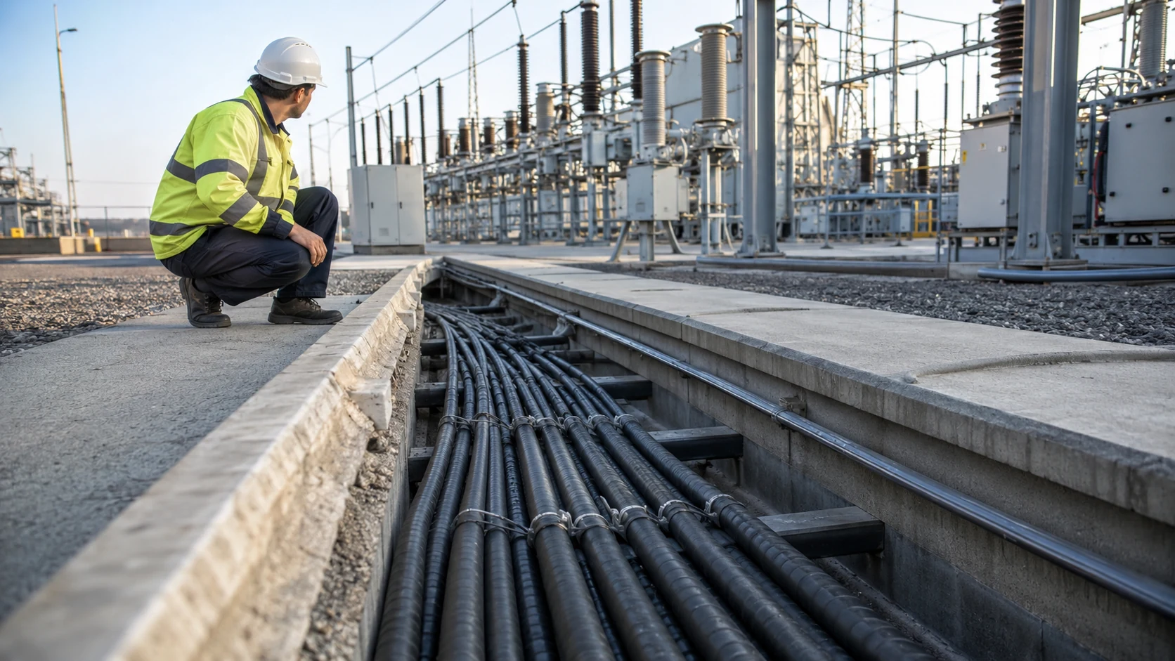
    High-voltage cable systems are increasingly critical to urban grids, renewable-energy connections, offshore wind farms and interconnectors. As power density rises, operators need more than periodic inspections. They need continuous information about where heat is building, whether a cable section is approaching its thermal limit and how loading affects long-term asset health. Distributed Temperature Sensing, or DTS, is one of the most powerful tools for this job.

    How DTS Works Along a Power Cable

    A DTS interrogator launches laser pulses into an optical fiber installed alongside or inside the cable system. Temperature changes affect the characteristics of backscattered light, allowing the system to calculate temperature at thousands of points along many kilometers of fiber. Instead of installing thousands of conventional temperature sensors, the fiber itself becomes a continuous sensing line.

    For power transmission operators, this creates a thermal profile of the complete route. Hot spots can be associated with joints, ducts, crossings, soil conditions, cable trays or other installation features. The key benefit is spatial awareness: the operator does not only know that a circuit is hot, but where the thermal constraint is developing.

    Dynamic Cable Rating

    One of the most valuable uses of DTS is dynamic cable rating. Traditional cable ratings are based on conservative assumptions about ambient conditions and heat dissipation. Real-time thermal data allows operators to estimate how much current can safely be carried under actual conditions.

    This can help utilities increase usable capacity without immediately replacing cables. It can also identify sections where poor thermal conditions are limiting the entire circuit. When combined with load data and thermal models, DTS becomes part of a real-time asset-management system rather than a simple alarm sensor.

    Where DTS Is Used

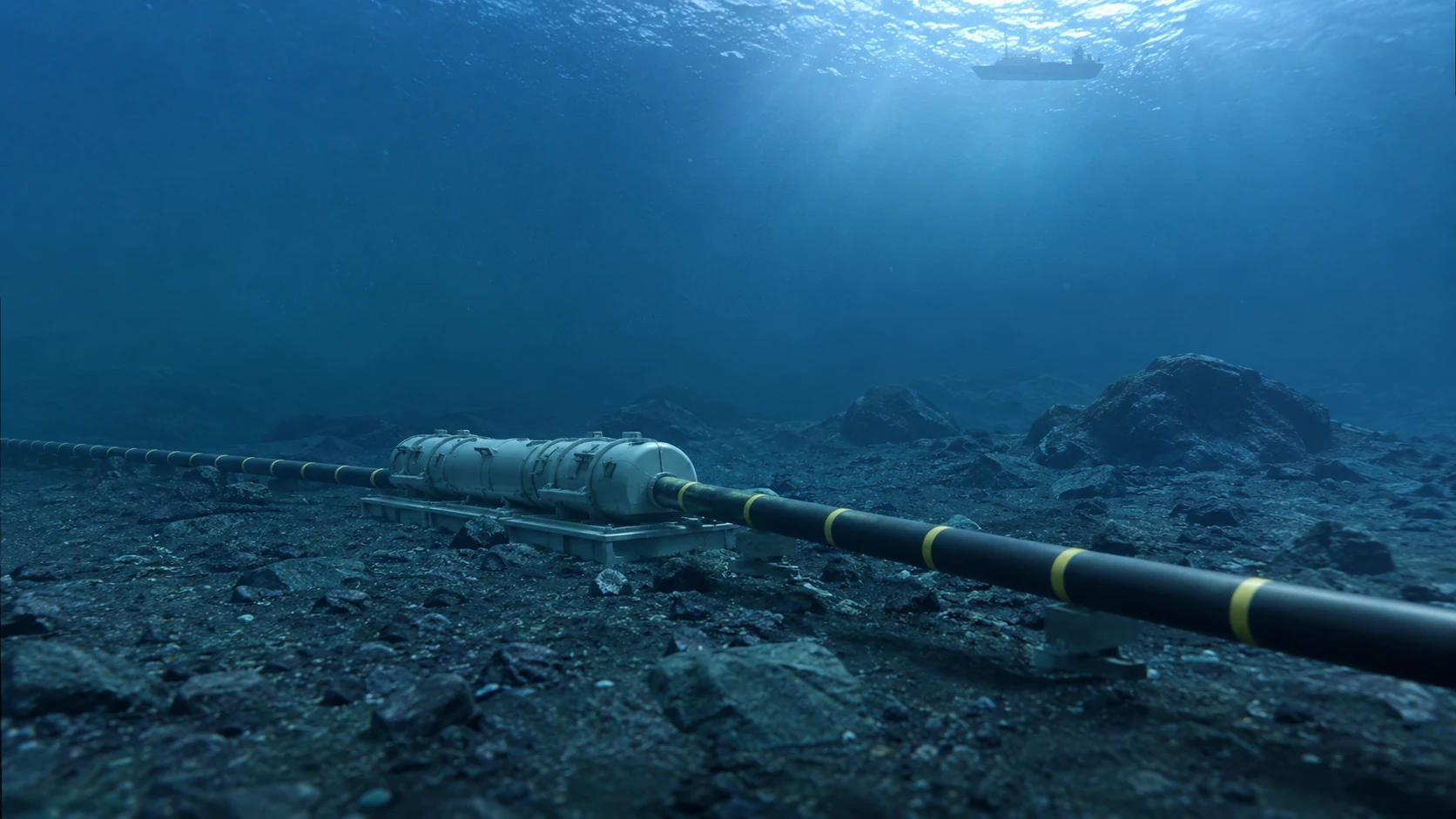
    Common applications include underground high-voltage cables, subsea export cables, tunnel installations, cable bridges, industrial power networks, data-center feeders and renewable-energy connections. It is especially useful on routes where conventional inspection is difficult or where failure would have severe operational consequences.

    Installation quality matters. The sensing fiber must have a known thermal relationship with the monitored cable. Calibration, route mapping, spatial resolution and integration with SCADA or condition-monitoring platforms all affect the quality of the final system.

    DTS vs Point Temperature Sensors

    Point sensors are valuable where a few specific components need monitoring, but they cannot provide a continuous thermal map. DTS is strongest when the asset is long and distributed. It can reveal unexpected heating between known inspection points and can provide historical temperature data for trend analysis.

    The two approaches are not mutually exclusive. Critical joints may use dedicated sensors while DTS monitors the complete route. A layered design often produces the best result.

    The Future: Combined Fiber-Optic Condition Monitoring

    The next step is combining DTS with other distributed fiber-optic sensing technologies. DAS can detect vibration and acoustic events, while distributed strain sensing can provide information about mechanical stress. Together, these technologies can create a multi-parameter view of cable health.

    For modern power networks, the optical fiber running beside a cable is becoming more than a communications channel. It can act as a continuous digital nervous system for the asset, helping operators improve capacity, detect abnormal conditions earlier and make better maintenance decisions.

    SectechMedia Editorial Note

    DTS should not be treated as a standalone thermometer. Its greatest value appears when thermal data is integrated with electrical load, cable models, alarms and maintenance workflows. In high-value cable systems, that integration can turn raw temperature measurements into actionable infrastructure intelligence.

  • DAS for Railway Monitoring: Train Tracking, Intrusion and Asset Awareness

    DAS for Railway Monitoring: Train Tracking, Intrusion and Asset Awareness

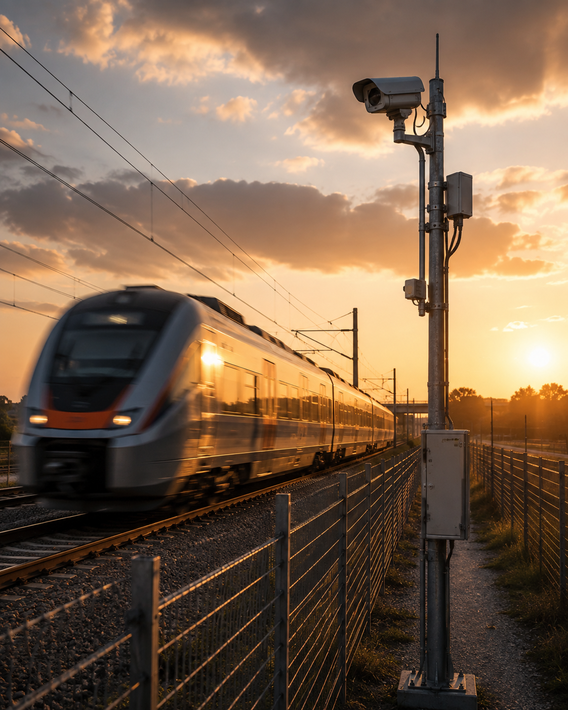
    Rail networks extend across long corridors that are difficult to monitor continuously with cameras and point sensors. Distributed Acoustic Sensing can use a fiber running beside the track to observe vibration along many kilometers from a single interrogator.

    Train detection and tracking A moving train generates a strong and characteristic vibration signature. DAS analytics can estimate its position, direction and speed as the signal moves along the fiber. This creates a distributed view of traffic even where no conventional trackside detector is installed.

    Trackside intrusion Footsteps, vehicles and activity near the railway can produce distinct patterns. A DAS system may help identify trespass, unauthorized maintenance activity or movement in protected areas. The exact detection performance depends on fiber placement, ground coupling and background vibration.

    Infrastructure condition awareness Changes in vibration patterns can also provide clues about track, wheel or infrastructure condition. Repeated measurements can be compared over time to identify unusual behavior. DAS should not be treated as a replacement for certified railway condition-monitoring systems, but it can add a valuable continuous data layer.

    Rockfall and environmental events In suitable installations, distributed sensing can identify ground vibration associated with rockfall, landslides or other events near the track. Combining DAS with weather, geotechnical and camera data can improve situational awareness on vulnerable routes.

    Existing telecom fiber Railways often already have optical fiber installed for signaling and communications. In some cases, spare fibers—or even fibers in existing cable routes—can be used for sensing. This can make large-scale pilots practical without building a new powered sensor network along the entire line.

    Analytics are essential Rail environments contain complex vibration from trains, road crossings, machinery and nearby communities. Event classification must be trained and validated against real local conditions. Alarm thresholds that work on one section of track may not be appropriate elsewhere.

    The broader opportunity is to transform railway fiber from a communications asset into a sensing infrastructure. With the right analytics and integration, the same corridor can support train awareness, intrusion detection, environmental monitoring and condition intelligence over distances that are difficult to cover with conventional sensors alone.

  • DAS for Pipeline Security and Leak Monitoring

    DAS for Pipeline Security and Leak Monitoring

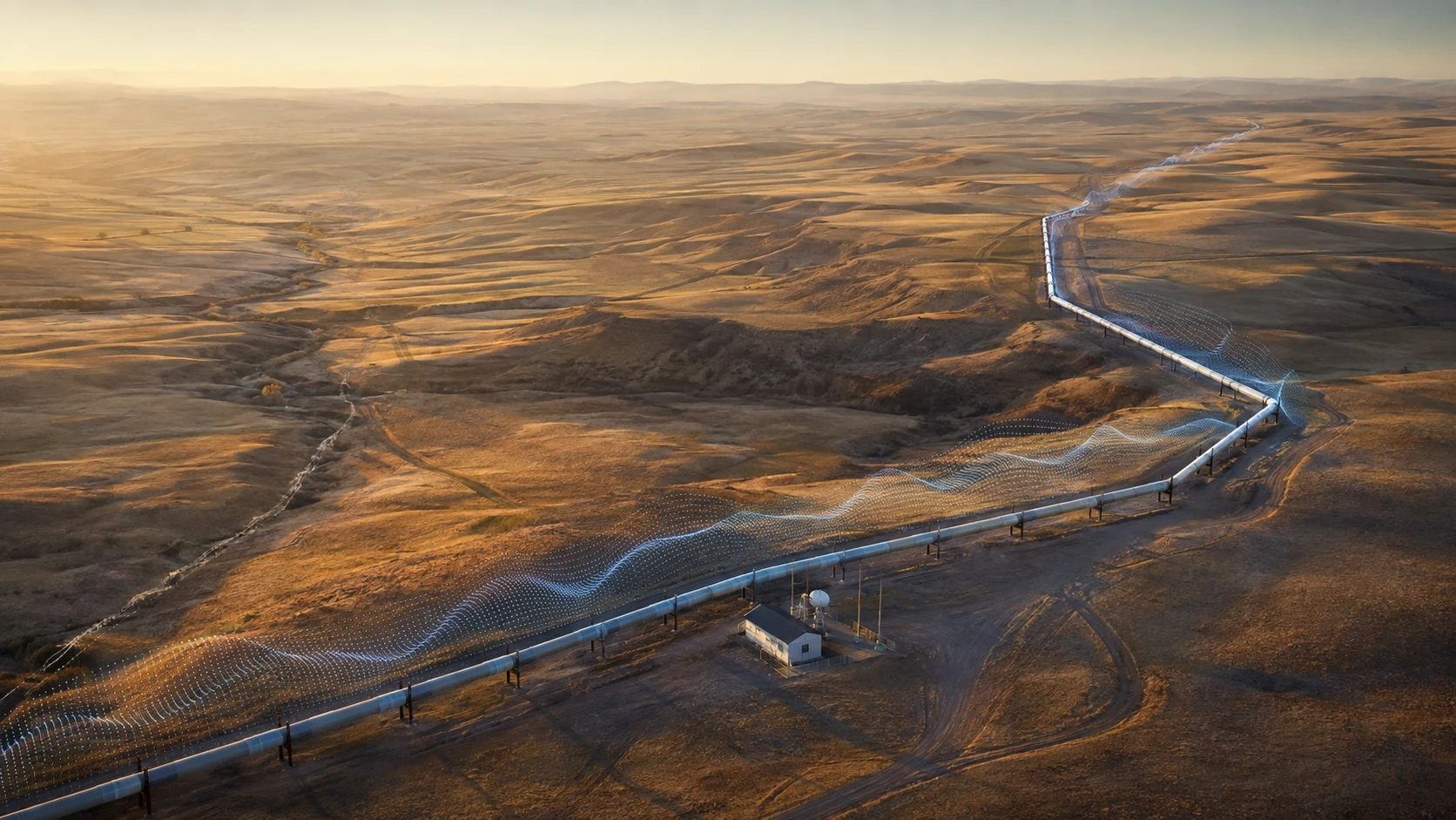
    Pipelines cross long, remote corridors where conventional point sensors and camera systems cannot provide continuous coverage. Distributed Acoustic Sensing offers a different model: a fiber installed along the route becomes a continuous vibration sensor capable of detecting and locating activity over many kilometers.

    Third-party interference Excavation is one of the most important pipeline risks. Digging, drilling, heavy vehicles and machinery create vibration signatures that can be detected before physical contact with the pipe occurs. A DAS system can identify the approximate location and generate an early warning for operators.

    Security applications The same sensing line can detect footsteps, vehicle movement, fence disturbance and other activity near above-ground facilities or rights-of-way. Classification software can distinguish many routine background events from activity that requires attention.

    Leak-related signatures Some leaks create acoustic or mechanical energy that couples into the pipe, surrounding soil or sensing cable. Depending on pipeline type, pressure, product, soil and cable installation, DAS can contribute to leak detection. It should not automatically be assumed to replace pressure, flow, mass-balance or other leak-detection methods; the strongest architecture often combines multiple independent indicators.

    Fiber placement and coupling Performance depends heavily on where and how the fiber is installed. A cable close to the pipeline and well coupled to the surrounding soil will respond differently from a telecom cable located farther away. Existing fibers may still be useful, but site testing is essential.

    Event classification Raw DAS data contains large amounts of vibration information. Analytics convert this data into operational categories such as excavation, vehicle, walking or background noise. Models need representative field data because soil, pipe construction, road traffic and industrial machinery vary from site to site.

    Integration with pipeline operations High-value alerts should be mapped into GIS and SCADA or security platforms so operators can see the event location, nearby assets and other sensor information. Cameras or patrol teams can then verify the alarm.

    DAS is particularly compelling for pipelines because one passive fiber can cover distances that would otherwise require thousands of powered field devices. Its greatest value is early, localized awareness: identifying potentially dangerous activity while there is still time to investigate and intervene safely.

    For further technology context, see FOTAS distributed fiber sensing and SAMM.

  • Rayleigh vs Raman vs Brillouin Scattering in Fiber Optic Sensing

    Rayleigh vs Raman vs Brillouin Scattering in Fiber Optic Sensing

    Distributed fiber-optic sensing works because a tiny fraction of light traveling through glass is scattered. Three names appear repeatedly in the field: Rayleigh, Raman and Brillouin scattering. Each mechanism carries different information and is therefore associated with different sensing applications.

    Rayleigh scattering Rayleigh backscatter is caused by microscopic variations in the refractive index of the glass. In coherent distributed sensing, changes in phase or interference patterns can reveal dynamic strain and vibration. This is why Rayleigh-based architectures are strongly associated with Distributed Acoustic Sensing.

    Raman scattering Raman scattering involves interaction between light and molecular vibrations. It creates Stokes and anti-Stokes components. The anti-Stokes response is strongly temperature dependent, allowing an interrogator to estimate temperature along the fiber. This principle is widely used in Distributed Temperature Sensing.

    Brillouin scattering Brillouin scattering results from interaction between light and acoustic waves inside the fiber. The frequency shift varies with temperature and strain. This makes Brillouin techniques useful for distributed strain sensing and combined temperature-and-strain monitoring.

    Why they should not be confused The three effects are all forms of optical scattering, but they produce different measurable signatures. Rayleigh is particularly useful for fast dynamic events. Raman is a mature basis for temperature measurement. Brillouin is valuable when absolute or slowly varying strain and temperature are important.

    Time-domain and frequency-domain methods Interrogators may use time-domain, frequency-domain or correlation-based processing. The scattering mechanism alone does not define the complete system. Pulse width, coherence, receiver design, signal processing and calibration all affect range and resolution.

    Hybrid sensing Some infrastructure projects combine multiple optical techniques. A power corridor might use DTS for cable temperature and DAS for intrusion or mechanical activity. A structural project may combine acoustic monitoring with strain sensing. The same route can therefore support several physical measurements.

    Understanding Rayleigh, Raman and Brillouin scattering helps explain why distributed fiber sensing is not a single product category. Different optical effects answer different engineering questions, and choosing the correct one begins with defining the physical quantity that must be measured.

  • How Optical Fiber Becomes Thousands of Distributed Sensors

    How Optical Fiber Becomes Thousands of Distributed Sensors

    An optical fiber is usually thought of as a communications medium. In distributed sensing, the same glass becomes a long chain of virtual measurement points. The key is that light traveling through a fiber is never perfectly isolated from the material around it: tiny amounts are scattered back toward the source.

    Time becomes distance A sensing interrogator launches short laser pulses into the fiber. Because the speed of light in glass is known, the system can estimate the location of a returned signal from the time it takes to come back. A reflection arriving later corresponds to a point farther along the fiber.

    Backscatter contains information Different scattering mechanisms respond to different physical effects. Rayleigh backscatter is widely used for acoustic and vibration sensing. Raman components are temperature sensitive. Brillouin scattering can be used to measure temperature and strain.

    Virtual channels Software divides the fiber into spatial sections. Each section behaves like a virtual sensor channel even though no electronic device has been installed at that position. A 20-kilometer fiber with meter-scale sampling can therefore represent thousands of measurement locations.

    Why this architecture is powerful The sensing element contains no distributed electrical power, processors or radio links. The complex electronics remain at the interrogator. This makes fiber attractive for tunnels, pipelines, railways, high-voltage corridors and remote infrastructure.

    Spatial resolution versus range Distributed sensing involves trade-offs. Higher spatial resolution, longer range, faster sampling and better signal-to-noise performance cannot always be maximized simultaneously. The correct configuration depends on whether the application needs fast vibration detection, accurate temperature measurement or slow structural strain monitoring.

    The cable installation also matters The fiber only measures what is mechanically or thermally coupled into it. A loosely installed cable may respond differently from one bonded to a pipe or buried in compacted soil. Cable construction, routing and installation are therefore part of the sensor design.

    This is the central idea behind distributed fiber-optic sensing: the fiber itself is not populated with thousands of conventional sensors. Instead, optical physics and time-of-flight processing make thousands of locations along one continuous fiber observable from a single interrogator.

  • DAS vs DTS vs DSS vs DTSS: Fiber Optic Sensing Explained

    DAS vs DTS vs DSS vs DTSS: Fiber Optic Sensing Explained

    Distributed fiber-optic sensing is not one technology. Several sensing methods use optical fiber to measure different physical effects along long distances. The most common terms are DAS, DTS, DSS and DTSS.

    DAS: Distributed Acoustic Sensing DAS measures dynamic strain and vibration. It is used to detect acoustic and mechanical events such as footsteps, digging, vehicles, trains, fence disturbance, machinery vibration and seismic activity. Many systems analyze coherent Rayleigh backscatter and can sample events at high frequency.

    DTS: Distributed Temperature Sensing DTS measures temperature continuously along a fiber. Raman-based systems are widely used for power cables, tunnels, pipelines, fire detection and industrial temperature monitoring. The output is a temperature profile rather than an acoustic waveform.

    DSS: Distributed Strain Sensing DSS measures static or slowly changing strain. Applications include structural monitoring, geotechnical movement, pipelines, bridges, dams and other assets where deformation develops over minutes, hours or longer periods. Brillouin scattering is commonly associated with this type of measurement, although architectures vary.

    DTSS: Distributed Temperature and Strain Sensing DTSS combines temperature and strain information, often through Brillouin-based measurements or hybrid configurations. Because temperature and strain can both influence the optical signal, system design and compensation methods are important.

    Different physics, different questions DAS asks: where is vibration occurring and what kind of event is it? DTS asks: where is the temperature changing? DSS asks: where is the fiber being stretched or compressed? DTSS seeks to characterize both temperature and strain.

    Can one fiber support several measurements? In some architectures, the same cable can support multiple interrogators or hybrid sensing systems. This allows an infrastructure owner to combine acoustic, temperature and strain information along the same route. Integration can create a richer condition-monitoring picture, but optical budgets, fiber allocation and system compatibility must be engineered carefully.

    The correct technology depends on the physical phenomenon that matters. A pipeline intrusion problem is usually acoustic; a power cable thermal-capacity problem is temperature-based; a slope movement problem may require strain. Understanding that distinction is the first step toward specifying the right distributed sensing system.

  • Distributed Temperature Sensing (DTS): Complete Technology Guide

    Distributed Temperature Sensing (DTS): Complete Technology Guide

    Distributed Temperature Sensing, or DTS, uses optical fiber as a continuous temperature sensor over long distances. Instead of installing individual electronic temperature probes every few meters, a single fiber can provide a temperature profile across cables, tunnels, pipelines, conveyors, storage areas and other extended assets.

    How DTS works Many DTS systems use Raman backscatter. A laser pulse travels through the fiber and a very small amount of light is scattered back toward the interrogator. The relative intensity of temperature-sensitive Raman components changes with the local fiber temperature. By measuring the return time, the system determines where along the fiber each temperature reading originated.

    Continuous temperature profiles The key advantage of DTS is not simply measuring temperature. It is seeing temperature as a continuous spatial profile. Operators can identify hot spots, compare zones, detect rate-of-rise conditions and follow thermal behavior over time.

    Power cable monitoring High-voltage cables are a major application. Cable loading capacity is influenced by conductor temperature, soil conditions, duct arrangement and surrounding thermal resistance. DTS can monitor the cable route and support dynamic cable rating, hotspot detection and asset-management decisions.

    Fire detection Linear heat detection with fiber is useful in tunnels, cable trays, conveyor galleries, warehouses and industrial facilities. Because the sensing fiber is passive and immune to electromagnetic interference, it can operate in environments where conventional electronics are difficult to deploy.

    Pipelines and industrial assets DTS can help identify temperature anomalies associated with leaks, process changes or insulation problems. In wells and pipelines, distributed temperature profiles provide information that would be impractical to obtain with sparse point sensors.

    Performance considerations Important parameters include sensing range, spatial resolution, temperature accuracy, measurement time and fiber configuration. Installation geometry and thermal coupling strongly influence how quickly the fiber reflects the temperature of the surrounding asset.

    DTS is most valuable when temperature is not a single point measurement but a distributed condition. By converting kilometers of passive optical fiber into a thermal map, it gives operators a continuous view of infrastructure that conventional sensors can only sample at selected locations.

  • Distributed Acoustic Sensing (DAS): Complete Technology Guide

    Distributed Acoustic Sensing (DAS): Complete Technology Guide

    Distributed Acoustic Sensing, or DAS, turns an ordinary optical fiber into a continuous line of virtual vibration sensors. Instead of placing thousands of electronic detectors along a pipeline, railway, fence or cable route, a DAS interrogator sends coherent laser pulses into the fiber and analyzes tiny changes in the backscattered light.

    How DAS works Most DAS systems rely on Rayleigh backscatter. Imperfections that naturally exist inside the glass return a very small portion of the launched optical energy. When vibration or strain changes the local optical path, the phase or intensity of the returned signal changes. By measuring the return time, the interrogator can estimate where along the fiber the disturbance occurred.

    One fiber, thousands of sensing points A major advantage of DAS is spatial coverage. A single interrogator can monitor many kilometers of fiber with virtual sensing channels distributed along the route. Spatial resolution, gauge length, sampling rate and total sensing range depend on system architecture and application requirements.

    What DAS can detect Typical event classes include footsteps, fence climbing, digging, vehicle movement, pipeline excavation, train movement, rockfall, cable activity, mechanical vibration and some leak-related signatures. The fiber does not directly identify an event; classification software interprets the vibration pattern.

    The role of AI Machine-learning models can separate relevant events from wind, traffic, machinery and other background vibration. Good performance still depends on installation quality, ground coupling, fiber position and representative training data.

    Applications DAS is increasingly used for pipeline security, railway monitoring, perimeter protection, power and telecom cable monitoring, seismic observation, subsea infrastructure and critical-infrastructure surveillance. Existing telecom fibers can sometimes be reused, reducing the need to install a separate sensor network.

    Limitations DAS performance is highly site dependent. Poor coupling can reduce sensitivity, while nearby machinery can create complex noise. Long sensing range may also require compromises in resolution or bandwidth. System evaluation should therefore be based on field trials and measurable detection requirements rather than headline range alone.

    Why DAS matters The strategic value of DAS is that the sensing element is passive fiber. It requires no electrical power along the monitored route and can provide dense, continuous awareness across distances that would be expensive to cover with conventional point sensors. As analytics improve, fiber networks are increasingly becoming infrastructure-intelligence networks rather than simple communication links.

  • AI-Assisted Evacuation Planning: Dynamic Routes and Safer Decisions

    AI-Assisted Evacuation Planning: Dynamic Routes and Safer Decisions

    Conventional evacuation plans are usually static. They assume designated exits, predefined routes and a limited number of emergency scenarios. Real incidents are dynamic: a corridor may fill with smoke, an escalator may stop, a crowd may block an exit or a secondary hazard may make the shortest route unsafe.

    What AI can add AI-assisted evacuation systems can combine data from fire alarms, smoke control, cameras, access control, occupancy sensors and building management systems. The objective is to estimate which areas are becoming unsafe and which routes remain available.

    Dynamic routing A digital building model can represent doors, stairs, refuge areas and travel distances. When live sensor data is added, software can recalculate recommended routes. Digital signage, mobile applications or voice systems can then direct different groups toward different exits.

    Crowd awareness Video analytics and occupancy sensors can estimate congestion. A route that is physically open may still be a poor choice if too many people are moving toward it. Dynamic planning can balance flow and reduce bottlenecks.

    Human factors Automation must not create confusing or contradictory instructions. People under stress tend to follow familiar routes and other people. Messages therefore need to be simple, consistent and supported by visible cues.

    Limits of AI Evacuation software cannot know every physical condition with certainty. Sensor failure, network loss or incorrect occupancy data can affect recommendations. For this reason, dynamic routing should supplement—not replace—code-compliant exits, passive fire protection and trained emergency procedures.

    The most promising use of AI is decision support. By combining real-time information with a verified building model, operators can understand changing conditions faster and communicate safer options. The goal is not autonomous evacuation; it is better situational awareness during the minutes when conditions are changing fastest.

  • Smoke Control Engineering for Large Buildings and Tunnels

    Smoke Control Engineering for Large Buildings and Tunnels

    In many fires, smoke creates the greatest immediate threat to occupants. It reduces visibility, carries toxic products of combustion and can make escape routes unusable long before flames reach them. Smoke-control engineering is therefore a central part of fire strategy in atriums, high-rise buildings, shopping centers, transit facilities and tunnels.

    The objective Smoke control is not simply about removing smoke as fast as possible. The engineering objective is to manage smoke movement so evacuation routes remain tenable, firefighting access is supported and smoke does not spread unnecessarily into protected areas.

    Pressure differential systems Stairwells, refuge spaces and selected corridors may be protected by maintaining positive pressure relative to the fire zone. The pressure must be high enough to resist smoke leakage but not so high that occupants cannot open doors.

    Mechanical smoke extraction Large spaces and tunnels often use dedicated exhaust fans, shafts and dampers to remove smoke from a defined zone. Replacement air must be carefully managed; poorly positioned make-up air can disturb the smoke layer and reduce system effectiveness.

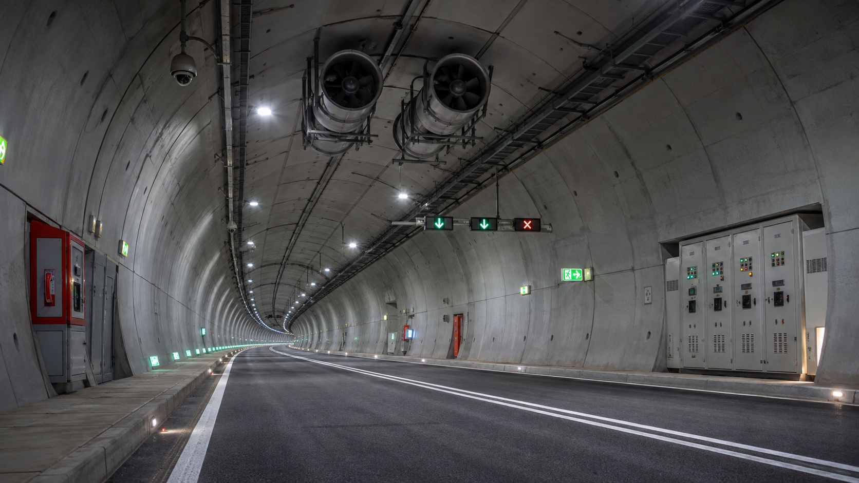
    Tunnels require a different approach In road and rail tunnels, longitudinal ventilation may be used to influence the direction of smoke movement. Jet fans, extraction points, fire location and traffic conditions all affect the strategy. The design must consider evacuation paths, cross passages and access for emergency services.

    Detection and controls A smoke-control system depends on reliable fire detection and correctly sequenced controls. Fans, dampers, doors, lifts and building management functions may all need to change state after a confirmed alarm. Cause-and-effect logic must be tested as a complete system, not as isolated components.

    Modelling and commissioning Computational fluid dynamics can help engineers study smoke movement in complex geometries, but modelling assumptions must be validated. On site, functional testing should verify airflow, pressure relationships, equipment response and emergency operating modes.

    A successful smoke-control design is therefore a combination of fire science, mechanical engineering, detection, controls and operational planning. Its real purpose is simple: preserve usable space and time for people to escape safely.