Category: Articles & Analysis

Long-form guides, explainers, comparisons, analysis and sector assessments.

  • LiDAR for Physical Security: Technology, Applications and Limitations

    LiDAR for Physical Security: Technology, Applications and Limitations

    LiDAR measures distance using laser light and can create a detailed three-dimensional representation of an area. In physical security, this supports detection and tracking based on geometry rather than visible appearance.

    How LiDAR works

    A sensor emits laser pulses and measures the time required for reflections to return. Repeated measurements create a point cloud showing the position of objects and surfaces.

    Security applications

    LiDAR can monitor entrances, facades, rooftops, restricted zones, warehouses and open areas. It can also support people counting, queue analysis and occupancy monitoring.

    Three-dimensional zones and privacy

    Virtual detection volumes can be created around assets, fences or doorways. Point clouds may represent people as shapes rather than conventional images, reducing identifiable visual data without removing privacy obligations.

    Limitations

    Heavy rain, fog, highly reflective surfaces and direct environmental conditions can affect performance. Range and point density vary between devices, and cost may exceed that of basic cameras or motion sensors.

    LiDAR, radar and video

    Radar often provides longer-range detection and stronger all-weather performance; LiDAR provides precise spatial detail; video provides texture, color and identity information. Combining them can improve tracking and verification.

    Conclusion

    LiDAR is most valuable where precise 3D awareness or privacy-conscious detection is important. Selection should follow site testing rather than generic range or accuracy claims.

  • Radar in Commercial Security: Where It Works Better Than Cameras

    Radar in Commercial Security: Where It Works Better Than Cameras

    Compact radar has become increasingly practical for commercial security. Modern sensors can detect, locate and track people or vehicles across wide outdoor areas, often in conditions where cameras struggle.

    How security radar works

    Radar transmits radio-frequency energy and analyzes reflections from objects. By measuring distance, angle and Doppler movement, a system can estimate a target’s position, speed and direction.

    Where radar outperforms cameras

    Radar does not depend on visible light and can operate in darkness. It can detect movement over wide open areas without requiring a detailed visual image, making it useful for large yards, airports, solar farms, ports, logistics areas and critical infrastructure.

    Tracking, verification and camera cueing

    Radar excels at tracking but does not provide identity. A visible or thermal PTZ camera can be cued automatically to verify a target and provide richer visual context.

    Coverage and nuisance alarms

    Vegetation, water, machinery, terrain, buildings and metal structures can affect performance or create shadow zones and reflections. Placement requires a site survey and realistic acceptance testing.

    Privacy, cybersecurity and integration

    Radar can support detection where continuous video raises privacy concerns, with video activated for verification. Networked radar also requires secure configuration, firmware management, segmentation and reliable VMS integration.

    Conclusion

    Radar is not a camera replacement. It is a complementary sensor that is often better at answering where a moving target is, how fast it is moving and where it is going.

  • Thermal Imaging in Security: Applications, Advantages and Limitations

    Thermal Imaging in Security: Applications, Advantages and Limitations

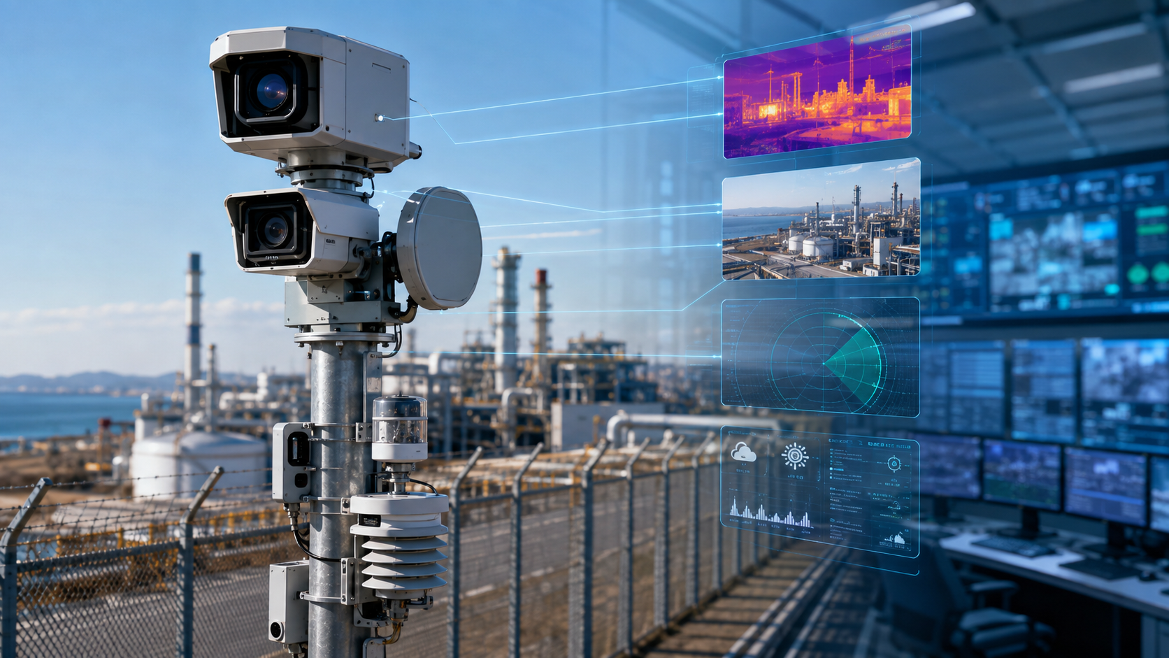
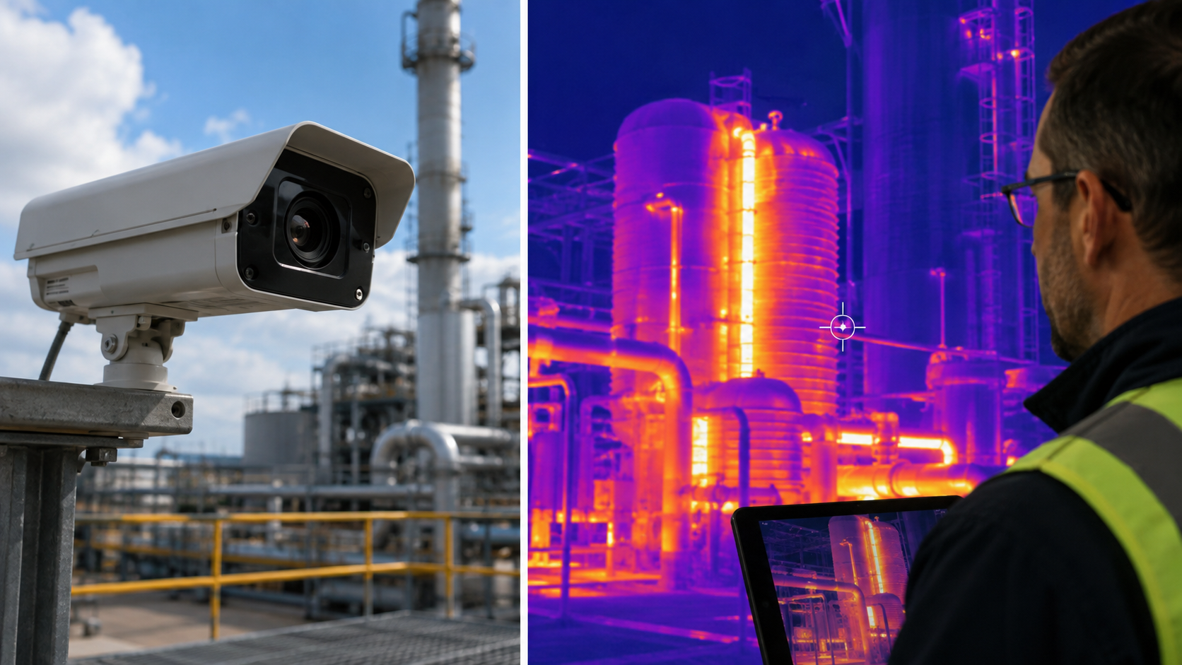
    Thermal cameras detect infrared radiation emitted by objects. Because they do not rely on visible illumination, they can detect people, vehicles and equipment in darkness and many difficult lighting conditions. Their strongest role is as part of a layered detection and verification architecture.

    Perimeter security

    Thermal imaging is especially valuable for perimeter detection. A person may appear as a clear heat contrast when a conventional camera sees only darkness. When paired with properly configured analytics, thermal cameras can classify targets and generate alarms for operator verification.

    Industrial monitoring

    Thermal cameras are also used to monitor electrical equipment, batteries, process machinery and storage areas for abnormal heat. In these applications, the same sensing platform can contribute to both safety and security operations. Temperature-related conclusions require equipment designed and configured for measurement, not merely thermal video.

    Performance in smoke, haze and low contrast

    Thermal imaging can sometimes provide useful visibility through light smoke, haze or difficult backlighting where visible cameras struggle. Performance still depends on atmospheric conditions, target contrast, wavelength and the characteristics of the scene.

    Advantages of thermal imaging

    • Operation without visible illumination
    • Strong contrast for many warm targets
    • Useful detection capability across large or remote areas
    • Potential privacy advantages where facial detail is unnecessary

    Important limitations

    Thermal cameras do not see through walls and cannot always identify a person. Glass may reflect or block thermal radiation depending on wavelength. Heavy rain, high humidity and extreme ambient temperatures can reduce effective detection performance. Thermal imagery also requires different interpretation from visible video.

    Radiometric and non-radiometric systems

    Some thermal cameras estimate temperature values, while others are intended only for imaging and detection. Temperature-measurement applications require suitable radiometric equipment, calibration, emissivity settings and environmental compensation. A non-radiometric security camera should not be treated as a precision temperature instrument.

    Analytics and seasonal testing

    Analytics can detect people or vehicles in thermal scenes, but training data and scene configuration matter. A system should be tested under representative seasonal and weather conditions because temperature contrast changes throughout the year.

    Integration with other sensors

    A common architecture uses thermal cameras for detection and visible PTZ cameras for verification. Radar can add tracking and range information. Combining complementary sensors can provide stronger situational awareness than relying on any single technology.

    Choosing a thermal camera

    Selection should begin with the required detection task, field of view, target distance, environmental conditions and integration workflow. Resolution, lens focal length, thermal sensitivity and environmental rating matter, but no single specification determines real-world performance.

    Conclusion

    Thermal imaging is a powerful specialized tool for physical security and industrial monitoring, but it is not a universal replacement for visible cameras. The best results come from risk-based design, realistic acceptance testing and integration with verification and response procedures.

  • Physical Security Technologies: From Fences to Ballistic Protection

    Physical Security Technologies: From Fences to Ballistic Protection

    Physical security is the combination of people, procedures, architecture, and technology used to protect people, facilities, operations, and assets from physical threats. It spans far more than cameras and access cards. A complete strategy can include site planning, fences, gates, lighting, intrusion detection, vehicle barriers, secure doors, glazing, ballistic-resistant assemblies, surveillance, communications, and trained response.

    The central design principle is layering. No single fence, sensor, lock, or rated material can address every threat. Effective protection uses complementary measures to deter an adversary, detect activity, delay progress, support assessment, and enable a proportionate response.

    Begin with risk, not equipment

    The U.S. Interagency Security Committee’s Risk Management Process frames facility protection around determining the facility’s security level, identifying risks, and selecting appropriate countermeasures. The same logic applies outside federal facilities: define what must be protected, identify credible threats and vulnerabilities, assess consequences, and then select measures that reduce risk to an acceptable level.

    A warehouse, data center, hospital, school, airport, power substation, and public venue require different designs. The objective is not to maximize visible hardware. It is to create a defensible system whose detection, delay, and response times work together.

    Site boundaries, fences, and controlled approaches

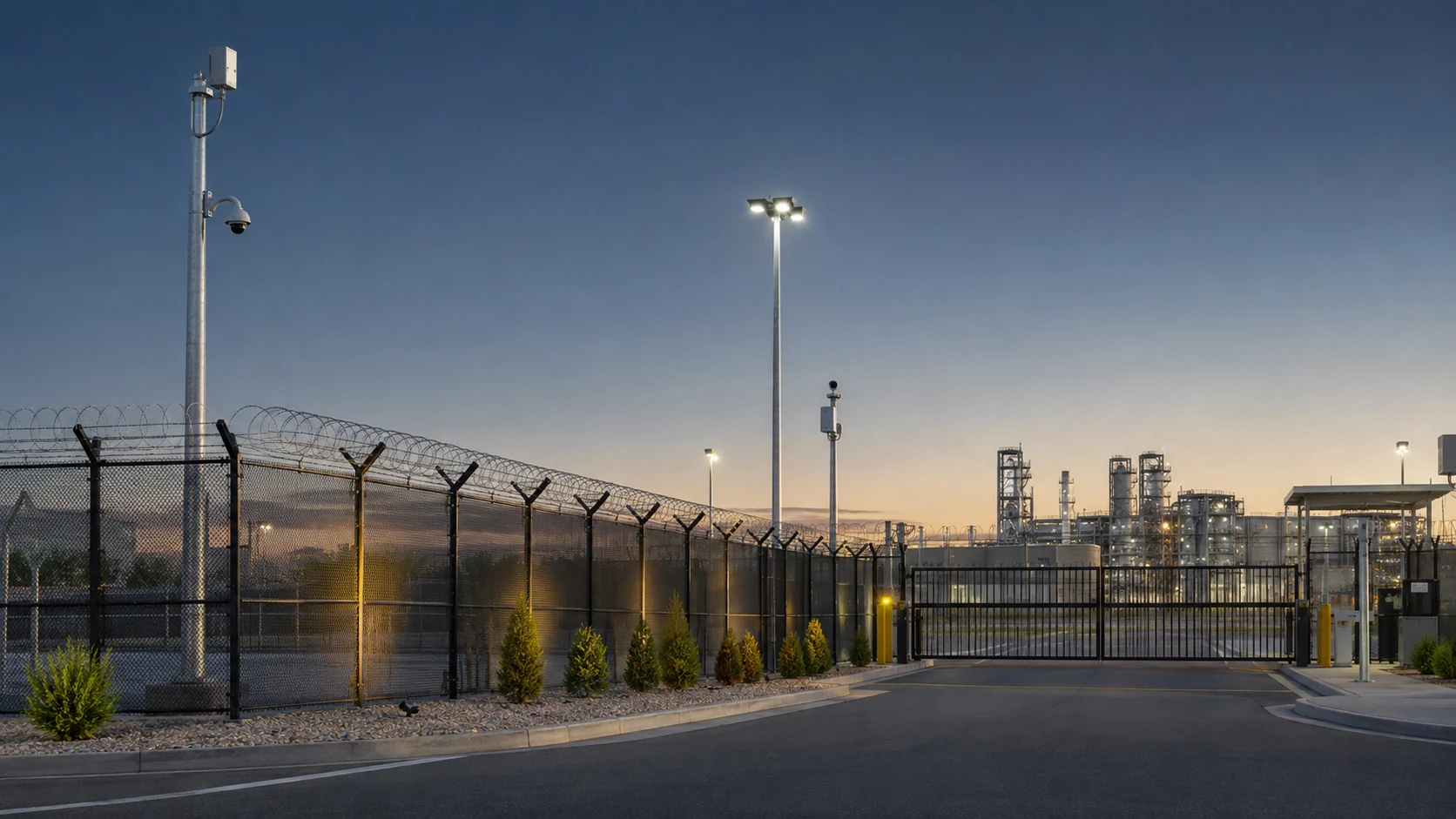
    Fences establish a boundary, channel movement, and can provide delay, but their performance depends on height, construction, foundations, gates, nearby climb aids, terrain, and inspection. The design should also preserve sightlines where surveillance and patrols need them. Landscaping, signage, and lighting can reinforce the boundary without creating concealment or unnecessary hazards.

    Gates are often more vulnerable than the fence line because they must support routine vehicle and pedestrian flow. Their locking, monitoring, safety controls, credentialing, and emergency operation should be treated as part of the security system rather than as standalone mechanical products.

    Vehicle barriers and hostile-vehicle mitigation

    Bollards, road blockers, wedges, gates, planters, reinforced street furniture, and landscape features can help keep unauthorized vehicles away from people or critical structures. The appropriate solution depends on the threat vehicle, approach geometry, available stand-off distance, traffic operations, emergency access, accessibility, drainage, utilities, and foundation conditions.

    Crash performance must be supported by the relevant test standard and rating for the intended scenario. ASTM F2656 addresses vehicle security barriers for medium-duty and heavy vehicles, while ASTM F3016 covers low-speed vehicle impact testing. A rating is not a universal promise: installation details, foundations, site geometry, and tested configuration matter.

    Doors, locks, access control, and compartmentation

    The building envelope continues the layered system. Doors, frames, hinges, glazing, locks, and surrounding construction should be considered as an assembly. A high-security lock installed in a weak door or frame does not create a high-security opening. Access control adds identity, authorization, event records, and centralized management, but mechanical egress, fire safety, fail-safe or fail-secure behavior, and emergency procedures remain essential.

    Inside a facility, zoning and compartmentation restrict movement after the outer boundary has been crossed. Critical rooms may need stronger construction, two-factor access, anti-tailgating measures, monitored doors, or local response procedures based on risk.

    Intrusion detection, surveillance, and assessment

    Detection technologies can include fence-mounted sensors, buried sensors, magnetic contacts, motion detectors, radar, thermal cameras, visible-light cameras, and distributed fiber optic sensing. Each responds to different physical phenomena and environmental conditions. Combining independent sensing modes can improve confidence, but only if alarm logic and operator workflow are designed to avoid overload.

    Surveillance supports assessment and investigation. It should be designed around operational tasks: detect a person or vehicle, recognize activity, identify a subject where lawful and necessary, verify an alarm, or reconstruct an event. Camera placement, lighting, field of view, pixel density, retention, cybersecurity, and operator workload are more important than simply maximizing camera count.

    Ballistic-resistant protection

    Ballistic-resistant glazing, opaque panels, doors, frames, transaction windows, and guard enclosures are used where a threat assessment identifies a firearms risk. The protection must be specified as a tested assembly for the relevant threat, not by vague labels such as “bulletproof.” UL 752 is one established standard for bullet-resisting equipment. NIJ Standard 0108.01 addresses ballistic-resistant protective materials, although project teams should confirm whether a newer or jurisdiction-specific requirement applies.

    Material selection alone is insufficient. Joints, frames, penetrations, mounting, supporting construction, spall behavior, visibility, weight, fire performance, and egress can determine whether the installed system performs as intended. Field modifications that differ from a tested construction require careful engineering review.

    Blast, forced-entry, and related threats

    Ballistic resistance, forced-entry resistance, and blast resistance are different performance requirements. A product tested for one should not be assumed to satisfy the others. Blast design may involve stand-off distance, structural response, façade and glazing behavior, fragment hazards, and progressive-collapse considerations. Forced-entry design focuses on resisting tools, impact, and sustained attack for a defined period. Where these hazards are credible, qualified specialists should translate the risk assessment into tested performance requirements.

    People, procedures, and response

    Technology cannot compensate for an undefined response. Alarm ownership, escalation, communications, guard deployment, law-enforcement coordination, visitor management, key and credential control, maintenance, and drills are part of the physical security system. CISA’s physical-security guidance repeatedly emphasizes understanding risk, planning, training, and layered protective measures.

    A useful timing model compares adversary progress with detection, assessment, communication, and response. Delay measures are valuable when they create enough time for a reliable response; delay without detection may simply postpone an unnoticed intrusion.

    Design and procurement checklist

    1. Define assets, threats, vulnerabilities, consequences, and operational constraints.
    2. Map public, controlled, restricted, and critical zones.
    3. Coordinate architecture, security, fire safety, accessibility, and emergency egress.
    4. Specify tested performance standards and the exact configurations required.
    5. Integrate detection, assessment, communications, and response procedures.
    6. Protect networked security devices and management platforms from cyber compromise.
    7. Commission the installed system with realistic tests, including degraded and emergency modes.
    8. Inspect, maintain, audit, and update the design as threats and operations change.

    FAQ

    Is a tall fence enough to secure a site?
    No. A fence can define a boundary and add delay, but gates, terrain, climb aids, surveillance, detection, lighting, inspection, and response determine the effectiveness of the perimeter.

    What is the difference between ballistic-resistant and blast-resistant construction?
    Ballistic resistance addresses projectile threats; blast resistance addresses pressure, impulse, fragments, and structural response. They require different tests and engineering.

    Do crash-rated bollards work in every installation?
    No. The tested barrier configuration, foundation, spacing, approach conditions, utilities, and installation quality all matter. The selected rating must match the design threat.

    Should security doors fail safe or fail secure?
    That decision depends on life-safety codes, occupancy, threat, operational requirements, and emergency procedures. Egress must never be treated as an afterthought.

    Conclusion

    Physical security works as a system of layers rather than a catalog of products. Fences, barriers, doors, sensors, surveillance, and ballistic-resistant assemblies each have a role, but their value depends on risk-based selection, tested performance, integration, and a credible human response. The strongest design is the one that protects the mission while preserving safety, accessibility, and normal operations.

    Sources and verification

    Verification note: No barrier, ballistic, forced-entry, blast, or detection rating is claimed for a specific product. Project requirements must reference current standards, the tested configuration, local codes, and qualified engineering.

  • Distributed Fiber Optic Sensing Explained

    Distributed Fiber Optic Sensing Explained

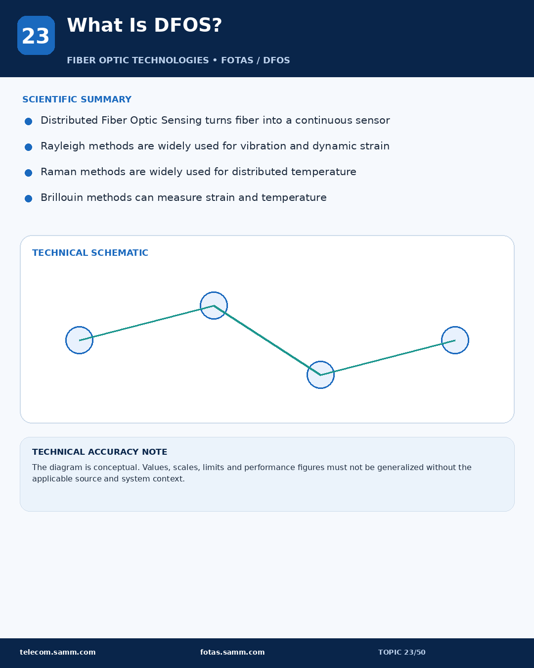
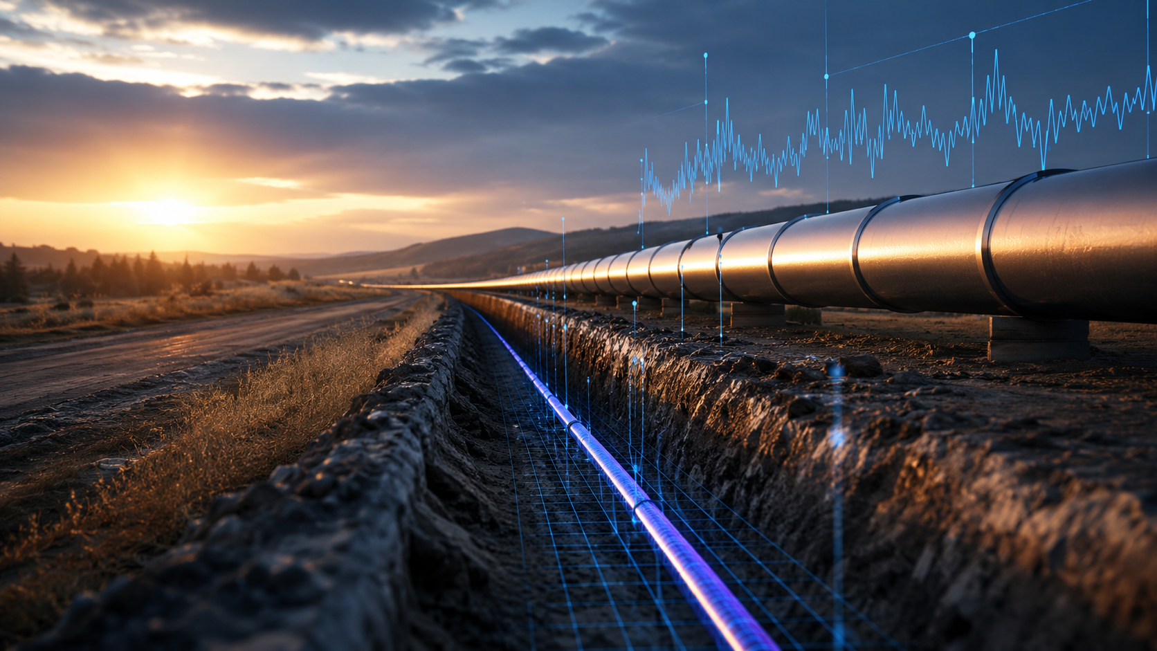
    Distributed fiber optic sensing (DFOS) turns an optical fiber into a continuous measurement line rather than using isolated electronic sensors at individual points. An interrogator launches light into the fiber and analyzes light that is scattered back from locations along the route. Because the return signal is associated with distance, one cable can provide spatially resolved information across a long asset.

    DFOS is an umbrella term. The three most common families are distributed acoustic sensing (DAS), distributed temperature sensing (DTS), and distributed strain sensing (DSS or DTSS when strain and temperature are measured together). They share an optical measurement architecture, but they do not measure the same physical quantity and should not be treated as interchangeable.

    How distributed fiber sensing works

    A typical system contains a sensing fiber or fiber-optic cable, an optoelectronic interrogator, signal-processing software, and an application layer that turns measurements into alarms, trends, or engineering information. The interrogator sends controlled optical pulses or frequency sweeps into the fiber. Microscopic variations in the glass scatter a small portion of the light back toward the instrument. By measuring the timing and characteristics of that return, the system estimates where a change occurred and what type of response the selected sensing method can reveal.

    This architecture is different from a string of conventional point sensors. The fiber itself provides measurement coverage along its route, while active electronics can remain at an accessible endpoint. However, the cable, installation method, coupling to the monitored asset, interrogation method, processing, and acceptance testing all influence performance.

    Rayleigh, Raman, and Brillouin scattering

    DFOS technologies are often described by the optical scattering mechanism they analyze. Rayleigh scattering is elastic scattering caused by small refractive-index variations in the fiber. Phase-sensitive Rayleigh techniques are widely associated with DAS because dynamic strain from vibration or acoustic energy changes the returned optical phase pattern.

    Raman scattering produces Stokes and anti-Stokes components. The relationship between those components is temperature-sensitive, which is why Raman-based systems are commonly used for distributed temperature measurement. Brillouin scattering is sensitive to both strain and temperature and is used in distributed strain and temperature measurements. A valid design must account for cross-sensitivity when the measurement responds to more than one physical quantity.

    DAS: distributed acoustic sensing

    DAS measures dynamic strain along the fiber and converts it into spatially resolved vibration or acoustic information. Security applications include perimeter activity detection, excavation and third-party-interference monitoring, and event awareness along pipelines, railways, borders, or other linear assets. Engineering applications include train tracking, traffic observation, seismic acquisition, and machinery-related monitoring.

    DAS does not literally turn fiber into a conventional microphone at every point. Its response depends on how strain is transferred into the cable, the orientation and frequency content of an event, environmental noise, optical conditions, gauge length, processing, and classification logic. A cable loosely placed in a duct may behave very differently from one mechanically coupled to a fence, buried beside a pipeline, or bonded to a structure.

    DTS: distributed temperature sensing

    DTS provides a temperature profile along the sensing route. Applications include fire and heat detection in tunnels, cable trays, conveyors, warehouses, and industrial facilities; thermal monitoring of power cables; process-vessel and well monitoring; and observation of heat movement in environmental and geotechnical studies.

    The U.S. Environmental Protection Agency describes fiber-optic DTS as a technique used in hydrogeological work to collect spatially and temporally dense temperature information. IEC 61757-2-2 specifies distributed temperature measurement by fiber-optic sensors. Those sources reinforce an important point: DTS is a measurement technology, while an alarm or diagnosis depends on application-specific thresholds, calibration, installation, and interpretation.

    DSS and distributed strain/temperature sensing

    Distributed strain sensing maps changes in strain along a fiber and can support structural and geotechnical monitoring. Use cases include deformation monitoring in tunnels, bridges, dams, slopes, foundations, pipelines, and other civil assets. Brillouin-based measurements may respond to both strain and temperature, so system design may require compensation, reference sections, or another way to separate the effects.

    Static or slowly changing strain measurement is not the same task as detecting fast vibration with DAS. Selection should begin with the measurand and required time behavior, not with the generic label “fiber sensing.”

    Where DFOS adds value

    • Long linear coverage: one sensing route can observe conditions across assets where dense point-sensor deployment would be difficult.
    • Passive field element: the optical fiber requires no electrical power at each measurement location.
    • Remote interrogation: active equipment can be placed in a controlled location while the cable follows a hazardous, remote, or inaccessible asset.
    • Spatial context: measurements can be displayed by distance, helping operators localize and compare events.
    • Multi-purpose infrastructure: in some projects, suitable existing fiber may support sensing, but feasibility must be confirmed through fiber characterization and field trials.

    Design limitations and trade-offs

    Performance figures are not universal. Sensing reach, spatial resolution, temperature or strain resolution, acoustic bandwidth, localization accuracy, and probability of detection depend on the interrogator, fiber and cable, optical loss, measurement settings, environment, installation geometry, and signal-processing requirements. Improving one parameter can reduce another; for example, longer reach or faster sampling may involve a resolution or signal-quality trade-off.

    DFOS also produces large data streams. A practical deployment needs alarm zoning, event classification, health monitoring, time synchronization, cybersecurity, retention rules, and integration with systems such as SCADA, GIS, video management, or security operations platforms. Site acceptance testing should use representative events and operating conditions rather than relying only on a laboratory specification.

    How to specify a DFOS project

    1. Define the physical quantity to measure: dynamic strain, temperature, static strain, or a combination.
    2. Describe the credible events and the response workflow after detection.
    3. Map the asset, fiber route, available fibers, splices, connectors, and expected optical loss.
    4. Design cable placement and mechanical or thermal coupling for the application.
    5. Set measurable acceptance criteria without assuming vendor claims are transferable between sites.
    6. Test representative events, background conditions, fault states, and integration paths.
    7. Plan ongoing calibration, model tuning, maintenance, and change control.

    FAQ

    Can ordinary telecommunications fiber be used for distributed sensing?
    Sometimes. Dark fiber or spare fibers may be usable, but cable construction, routing, splices, optical loss, access, and coupling to the monitored environment must be assessed. A communications route that is excellent for data transmission is not automatically a good sensing installation.

    Are DAS, DTS, and DSS interchangeable?
    No. DAS is generally used for dynamic strain and vibration, DTS for temperature, and DSS for distributed strain. The interrogator, processing, cable design, and installation must match the measurand.

    Does DFOS eliminate conventional sensors?
    Not necessarily. Point sensors may provide direct measurements, local redundancy, or calibration references. Hybrid architectures often combine distributed and point sensing.

    Can one fiber support both communications and sensing?
    Some architectures can share infrastructure or use different fibers within the same cable, but optical compatibility, network ownership, operational risk, and performance must be engineered and tested.

    Conclusion

    Distributed fiber optic sensing provides a powerful way to observe temperature, strain, vibration, and acoustic activity along extended assets. Its value comes from continuous spatial coverage and a passive sensing medium, not from a universal performance guarantee. Successful projects begin by selecting the correct sensing family, engineering the fiber’s relationship to the asset, and validating the complete detection-to-response workflow under real conditions.

    Sources and verification

    Verification note: No product-specific sensing range, resolution, accuracy, channel count, or detection-performance claim is presented. Those values must be verified for the selected interrogator, fiber, installation, and application.

  • Counter-UAS Technology: A Complete Guide to Drone Detection and Protection

    Counter-UAS Technology: A Complete Guide to Drone Detection and Protection

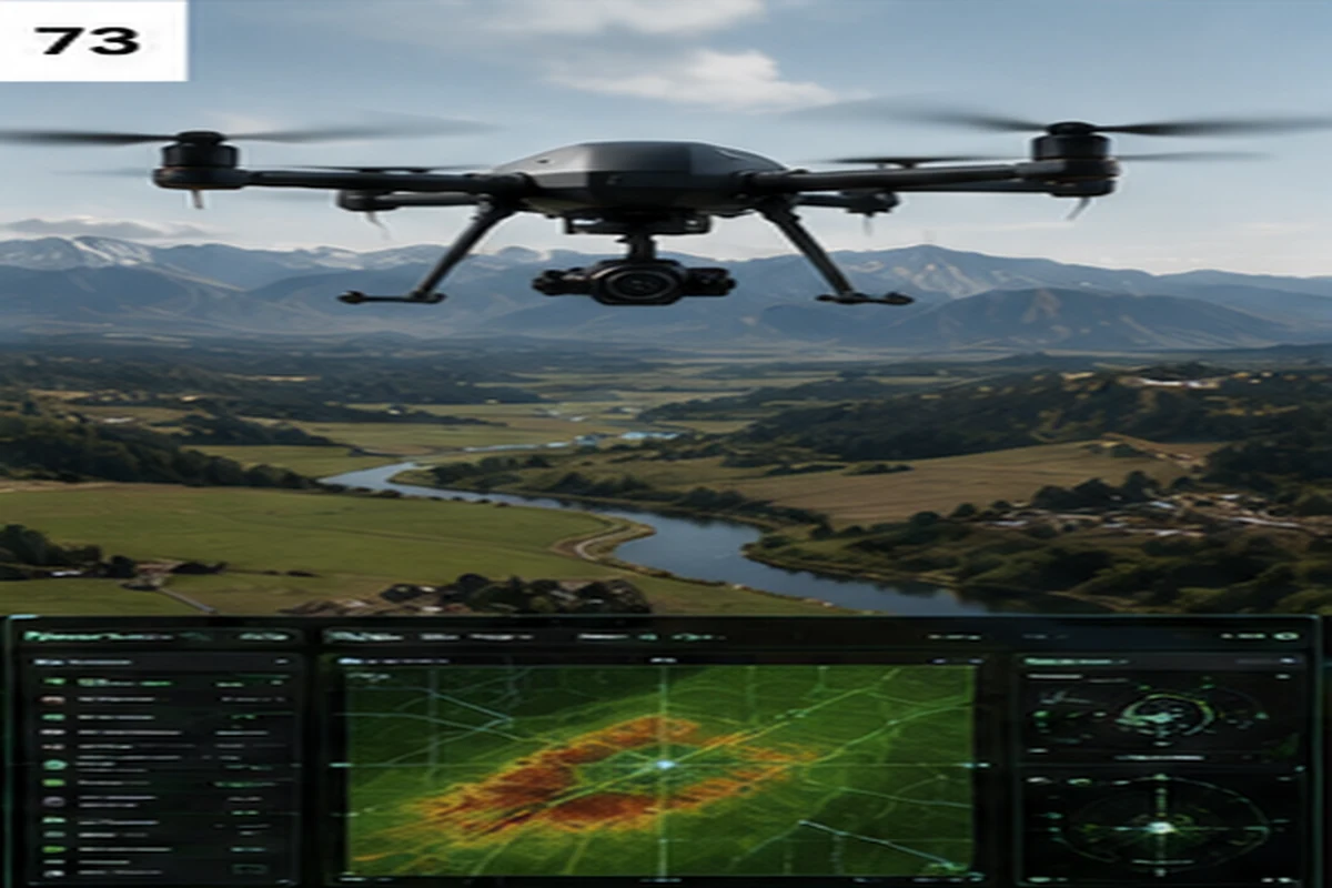
    Consumer and commercial drones have become cheap, capable and easy to fly, and that combination has turned unauthorized small unmanned aircraft into a real risk for airports, stadiums, prisons, power plants and other sensitive sites. Counter-UAS (C-UAS) technology is the set of systems built to detect, track, identify and — where legally authorized — mitigate that threat. This guide explains how the major detection layers work, why no single sensor is enough on its own, and what to weigh before deploying a system.

    What counter-UAS technology actually does

    A counter-UAS deployment is usually described as a four-stage pipeline: detect that an unmanned aircraft is present, track its position and movement over time, identify what kind of drone it is and whether it represents a threat, and — only where the operator is legally authorized to act — mitigate it. Most commercial and critical-infrastructure deployments stop at detect/track/identify; active mitigation such as jamming or physical interception is heavily restricted and, in many jurisdictions, reserved for military, law enforcement or specifically authorized government operators.

    The four main detection layers

    Real-world counter-UAS systems combine more than one sensor type, because each has a different blind spot.

    Radio frequency (RF) detection passively listens for the control and video-link signals between a drone and its operator. It is often the first layer deployed because it is passive, relatively low cost, and can identify a drone’s make and model — and sometimes locate the operator — from its known RF signature. Its limitation is structural: a drone flying a pre-programmed autonomous route with no active control link, or one that is RF-silent by design, will not appear on an RF-only system.

    Radar actively illuminates the airspace and detects the reflection, so it finds drones regardless of whether they are transmitting. It can track multiple targets simultaneously, which matters for swarm scenarios, but small consumer drones have a much smaller radar cross-section than aircraft, so effective range for that target class is typically much shorter than a radar’s rated range for larger objects.

    Electro-optical and infrared (EO/IR) cameras provide visual or thermal confirmation of a detected track. In most architectures EO/IR is a “slew-to-cue” layer — pointed at a target after RF or radar has already found it — rather than a primary wide-area search sensor, because scanning a full sky visually is slow and unreliable compared with RF or radar detection.

    Acoustic sensors use microphone arrays to recognize the sound signature of rotors and propellers. They are passive and comparatively inexpensive, and can work in some non-line-of-sight and low-light conditions, but they are short-ranged and lose reliability near traffic, generators or crowd noise.

    Why layered, fused sensing is the standard

    No single sensor type covers every scenario, so credible counter-UAS architectures fuse two or more layers rather than relying on one “magic” detector: RF for early warning and identification, radar for RF-silent and autonomous drones, EO/IR for visual verification, and sometimes acoustic sensing as a supplementary layer in quiet environments. A command-and-control platform then fuses detections from each sensor into a single track — without fusion, the same drone can appear as several separate, unconnected alerts, which confuses operators and inflates the apparent scale of a threat.

    Mitigation: the heavily regulated final layer

    Once a drone is detected, tracked and identified as a genuine threat, mitigation options include RF jamming of the control link, GPS spoofing, high-power microwave devices, physical interceptors such as nets, and — at the most restrictive end — kinetic or directed-energy countermeasures. In most countries these active measures are tightly controlled by aviation and telecommunications law, because jamming or disabling an aircraft can also affect nearby legitimate air traffic and communications. Any organization evaluating counter-UAS technology should confirm what it is legally permitted to do at its specific site before assuming a detection system also gives it the right to act.

    Where counter-UAS technology is deployed

    Typical deployment sites include airports (where unauthorized drones can force runway closures), stadiums and large public events, correctional facilities (where drones have been used to smuggle contraband), critical infrastructure such as power plants and data centers, and government or military installations. The right sensor mix depends heavily on the site: an airport needs detection that will not generate false alarms from its own radar clutter and air traffic, while a rural substation may prioritize long-range RF and acoustic coverage over a wide, low-traffic perimeter.

    What to check before choosing a system

    Vendor-quoted detection ranges are typically measured in flat, dry, radio-quiet test conditions. Real-world range at a specific site is reduced by urban RF noise, terrain masking and antenna or mast height, so it is worth asking for performance figures at a comparable site profile rather than a datasheet maximum. It is also worth asking how a vendor maintains its RF and radar signature library, since new consumer drone models are released constantly and a detection library that is not actively updated will miss them. Finally, confirm the legal authorization required for any mitigation capability before including it in a procurement — detection and identification are usually far less regulated than active response.

    FAQ

    Is RF detection alone enough? No. RF detection misses autonomous or pre-programmed drones that are not actively transmitting to a controller, which is why radar or EO/IR coverage is normally paired with it.

    Can a business legally jam or shoot down a drone? In most jurisdictions, no — active mitigation is restricted to authorized government, military or law-enforcement operators. Commercial sites typically deploy detection, tracking and identification, then hand off to authorities for response.

    What is the single most important design decision? Matching the sensor mix to the site’s terrain, RF environment and threat profile, rather than deploying one sensor type everywhere. A layered, fused approach consistently outperforms any single technology.

    Verification note: This guide describes counter-UAS technology at a general, technology level. It does not cite specific vendor products, performance claims or deployment case studies, since those figures vary by manufacturer and require independent verification before publication.

  • Airport Security Projects: What Major Airport Expansions Need Beyond Cameras

    Airport Security Projects: What Major Airport Expansions Need Beyond Cameras

    A practical guide to the security, fire, access, screening and command systems typically required in major airport expansion projects.

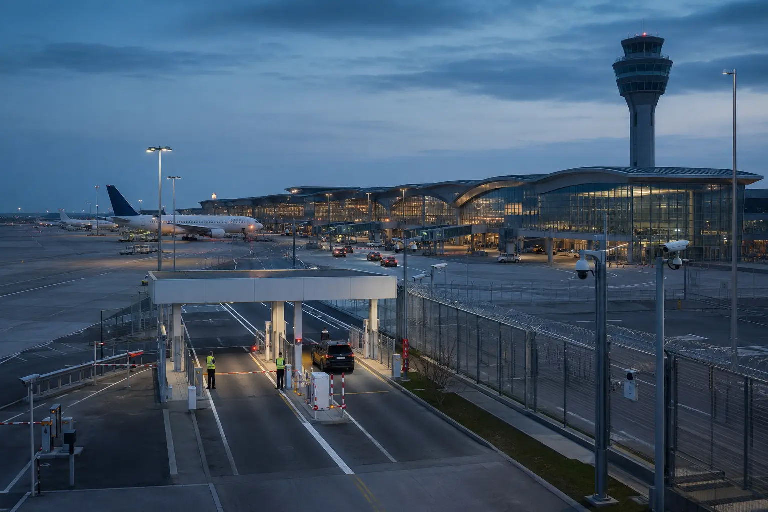
    Airport projects are often described in terms of terminals, runways and passenger capacity. For security professionals, however, the more interesting question is what sits behind those structures: how are restricted zones protected, how is passenger flow screened, how are service tunnels monitored, and how are thousands of alarms unified in one operating picture?

    A modern airport project can involve video surveillance, access control, perimeter intrusion detection, explosive and baggage screening, vehicle barriers, fire detection, smoke control, emergency communication and command-and-control platforms. The challenge is not simply selecting devices. Airports are live environments with aviation regulations, multiple tenants, public areas, sterile zones, airside operations and critical utilities. Integration becomes as important as individual product performance.

    Project intelligence should therefore track packages, not only the headline project. A terminal expansion may create separate opportunities for CCTV, access, fire alarm, baggage screening, communications, tunnel safety and perimeter upgrades. Transport projects that intersect with an operating airport — such as new transit links built through station boxes and tunnel portals — show how construction and aviation security can become interlinked. That type of interface is exactly where security and life-safety design becomes complex.

    Why it matters

    Airport projects are long-cycle, multi-package opportunities. For integrators and manufacturers, understanding project stage and package structure can be more useful than knowing the total project value.

    Verification note

    Project-specific facts (contract values, timelines, named contractors) must be verified against airport authority, transport authority and tender documents before being reported as current news. This overview describes general project structure only.

  • VMS, PSIM and Command & Control Systems Explained

    VMS, PSIM and Command & Control Systems Explained

    Understand how VMS, PSIM, alarm management, GIS, sensor fusion and security operations center platforms turn security data into operator decisions.

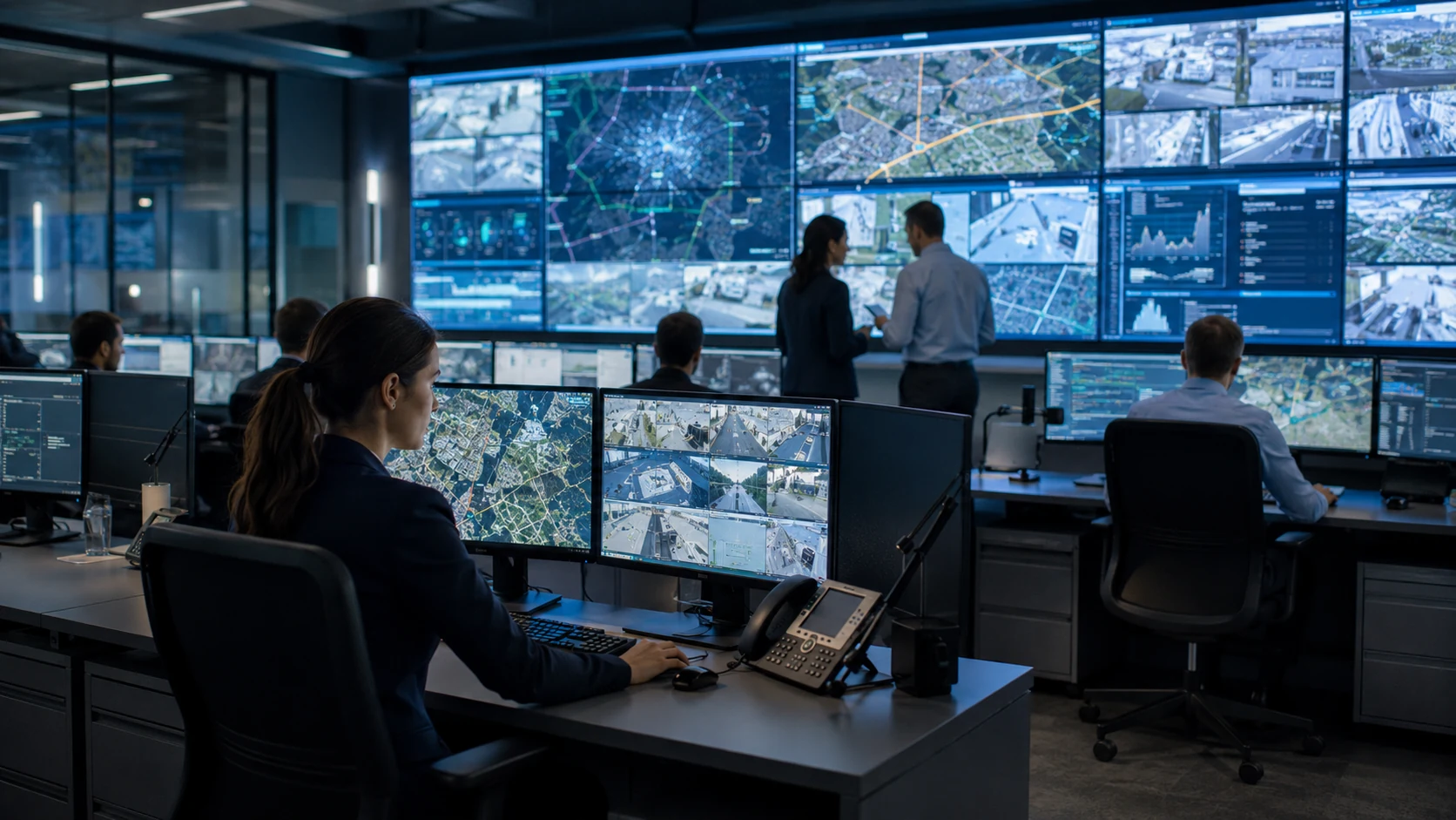
    Security technology produces events faster than people can interpret them. Cameras create video and metadata, access systems create credential events, perimeter sensors create alarms, fire systems create life-safety signals and building systems add another layer of operational data. Command-and-control software exists to turn that flow into a manageable picture.

    VMS: video first

    A Video Management System is primarily designed to manage video. It connects cameras, controls streams and recording, manages users, displays live and recorded video, and increasingly hosts analytics and integrations. For many sites, the VMS is the main operator interface because visual verification is central to incident response.

    Modern VMS platforms often integrate access control, intercom and analytics, but the depth of those integrations varies. A system that can display an access alarm is not necessarily a full access-control platform.

    PSIM: process and integration first

    Physical Security Information Management was developed to aggregate events from multiple security systems and guide operators through consistent procedures. A PSIM may sit above VMS, access control, intrusion, fire interfaces, GIS and other systems. The key value is not simply showing everything on one screen; it is correlating events, applying rules and creating an auditable response workflow.

    For example, a perimeter radar detection might automatically cue a PTZ camera, display the target on a map, check nearby access-control states and present the operator with a response procedure. That is more useful than five independent alarms arriving in five applications.

    Command & control

    The term command and control is broader. In critical infrastructure or public-safety environments, the platform may combine security, operational technology, communications, mapping, incident management and external data. The design goal is shared situational awareness and coordinated action.

    Alarm management and prioritization

    A common failure in security operations centers is alarm overload. If low-priority technical faults are presented with the same urgency as a confirmed intrusion, operators lose attention. Good alarm management applies severity, confidence, location, time, dependencies and escalation rules.

    Sensor fusion goes further by combining evidence. A single radar track may be interesting; a radar track plus thermal detection plus a fence vibration event is more compelling. Fusion logic should be transparent enough for operators to understand why the system raised priority.

    Interoperability and metadata

    ONVIF Profile M standardizes metadata and events for analytics applications and can help move structured information between compatible systems. Standardized event data matters because automation depends on software understanding not just a video stream, but what the system believes happened.

    GIS and maps

    Maps are particularly useful for large campuses, airports, borders and energy sites. Spatial context allows operators to see where alarms occur relative to gates, cameras, patrols and assets. Good GIS integration should support action, not just decoration.

    How to choose the right layer

    A small site may need only VMS plus integrated access control. A larger enterprise may benefit from a unified security platform. A critical-infrastructure operator with many legacy systems may need PSIM or a broader command-and-control layer.

    The key questions are operational: how many systems must operators use, which events need correlation, what workflows must be enforced, how incidents are escalated and what evidence is required afterward.

    FAQ

    Is PSIM the same as VMS? No. VMS is video-centric; PSIM is typically multi-system and workflow-centric, though modern platforms increasingly overlap.

    What is sensor fusion? It is the combination of signals or events from multiple sensors to improve confidence or context.

    Does one interface guarantee integration? No. True integration should be evaluated at the data, control and workflow levels.

    Verification note

    Avoid claiming a “single pane of glass” unless a tested integration actually supports the required control functions, not just event display. This article describes general architecture, not vendor-specific performance claims.

  • Security Screening Technologies Explained: X-Ray, CT, Metal and Trace Detection

    Security Screening Technologies Explained: X-Ray, CT, Metal and Trace Detection

    Learn how X-ray, CT, metal detection, explosive trace detection, radiation detection and vehicle screening technologies are used in security checkpoints.

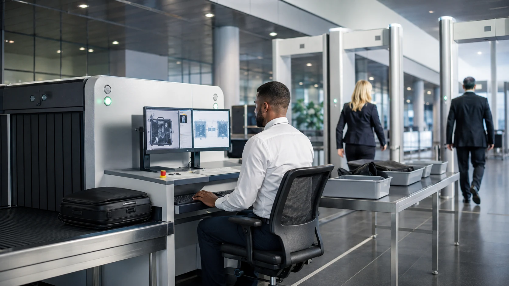
    Security screening is about finding prohibited or dangerous items without turning every checkpoint into a manual search. That sounds straightforward, but different threats interact with matter in different ways. A metal detector is useful for conductive metal objects; an X-ray system reveals differences in material density and composition; explosive trace detection looks for microscopic chemical residues. There is no single screening technology that reliably answers every threat question.

    X-ray screening

    Conventional X-ray systems send radiation through an object and measure how materials attenuate the beam. Operators interpret the resulting image, often with software that highlights material groups or suspicious regions. X-ray is widely used for baggage, parcels, cargo and mail because it allows inspection without opening every item.

    Image quality depends on generator geometry, detector performance, object density and viewing angle. Dense objects can obscure material behind them, which is why dual-view and multi-view architectures can improve assessment. Automated detection algorithms can assist operators, but final performance still depends on threat libraries, system configuration and human interpretation.

    Computed tomography

    CT screening takes multiple X-ray projections and reconstructs a three-dimensional representation of an object. That gives screening software more information about shape and density than a single projection. TSA has deployed CT equipment at passenger checkpoints and has described it as advanced checkpoint screening technology. The value is not simply a prettier image: 3D reconstruction can support automated threat recognition and allow operators to rotate or inspect virtual slices of a bag.

    Walk-through and handheld metal detection

    Metal detectors create an electromagnetic field and sense disturbances caused by conductive objects. Walk-through systems are suited to high-throughput personnel screening, while handheld detectors are used for secondary inspection and localization.

    Sensitivity is a trade-off. A system tuned aggressively may detect smaller objects but create more alarms from harmless personal items. Screening policy, threat model and expected throughput need to be considered together.

    Explosive trace detection

    ETD systems analyze tiny residues collected from surfaces, bags or hands. The technology is useful because it looks for chemical evidence that may not be visually obvious. It is typically a secondary method rather than a universal replacement for imaging. Sampling technique, contamination control and environmental conditions can influence results.

    Radiation and nuclear detection

    Radiation portal monitors and handheld instruments detect ionizing radiation associated with radioactive materials. These technologies are important at borders, ports, critical facilities and special events, but the screening problem is complex because legitimate medical or industrial sources can also produce radiation. Detection must therefore be linked to identification and response procedures.

    Vehicle and cargo inspection

    Large-scale X-ray or gamma-based systems can inspect vehicles, trucks and cargo containers. Under-vehicle inspection systems use cameras or scanners to inspect vehicle undersides for anomalies. Automatic number-plate recognition can add identity and movement history, but it is not itself a contraband detector.

    Why layered screening matters

    Checkpoint design should combine technologies based on the threat. A high-security facility may use identity verification, walk-through metal detection, bag X-ray, trace detection and secondary manual inspection. An airport may apply different screening to passengers, checked baggage, cargo and staff.

    The goal is not to maximize the number of machines. It is to create a sequence in which one technology compensates for another’s blind spots while keeping throughput acceptable.

    FAQ

    Is CT better than X-ray? CT provides richer 3D information, but “better” depends on the screening application, throughput, cost and detection requirements.

    Can a metal detector find explosives? It detects metal, not explosive chemistry. Explosive threats may require imaging, trace detection or other methods.

    Can AI replace screening operators? Automated detection can assist, but operational procedures, secondary screening and trained human judgment remain important.

    Verification note

    Detection probabilities and false-alarm figures must come from validated test programs for specific devices; figures in this article avoid vendor performance claims and general industry description only.

  • Access Control and Identity Technologies Explained

    Access Control and Identity Technologies Explained

    A practical guide to access control, credentials, mobile access, biometrics, readers, controllers, locks, visitor systems and interoperability.

    Identity and credential are not the same thing

    An identity represents a person, role or sometimes a vehicle or device. A credential is the token used to claim that identity. Traditional credentials include proximity cards and smart cards; newer systems use smartphones, digital wallets or biometrics. A credential alone does not prove that the correct person is presenting it, which is why higher-security applications may combine something a user has with something they are or something they know.

    Readers and controllers

    The reader captures the credential. The access controller applies rules and makes or supports the authorization decision, either locally at the door, by a central server, or through a hybrid model. Local intelligence matters for resilience: critical doors may need to continue operating against locally stored permissions if the network becomes unavailable.

    Locking hardware

    The electronic system ultimately controls physical hardware: electric strikes, magnetic locks, motorized locks, turnstiles or speed gates. Life-safety and egress requirements can override security logic, so door hardware selection must consider local fire and building codes as well as security.

    Interoperability

    Multi-vendor access control has historically required significant custom integration. ONVIF Profile A defines functions for configuring credentials, schedules and access rules; Profile C covers basic door control and event management; Profile D supports peripherals such as readers, biometric devices, keypads and locks. ONVIF’s access-control specifications have also been adopted into IEC 60839-11-1 requirements.

    Mobile credentials and biometrics

    A smartphone can act as a credential using technologies such as NFC or Bluetooth, simplifying issuance and revocation. Fingerprint, face and iris systems bind access decisions more closely to the person rather than the token, but introduce privacy, accuracy and governance questions—matching thresholds affect the trade-off between false accepts and false rejects.

    How to design a system

    Begin with access policy, not hardware. Define zones, user groups, schedules, exception handling, emergency behavior, visitor processes and audit requirements. Only then choose credentials, readers, controllers and software. The real security value of an access-control system is making authorization consistent, reviewable and resilient across the life cycle of every identity.

    FAQ

    Are mobile credentials replacing cards? They are growing quickly, but cards will remain relevant in many environments because of cost, legacy infrastructure, user requirements and offline operation.

    Is facial recognition the same as access control? No. Facial recognition can be one authentication method within an access-control system.

    What is ONVIF Profile A? It is an ONVIF profile for access-control configuration, including credentials, schedules and access rules.

    Verification note: Local egress and fire-code requirements must be checked before publishing hardware recommendations for controlled doors.