Category: Emergency & Life Safety

  • Smoke Detector Sensitivity Testing and Contamination Maintenance

    Smoke Detector Sensitivity Testing and Contamination Maintenance

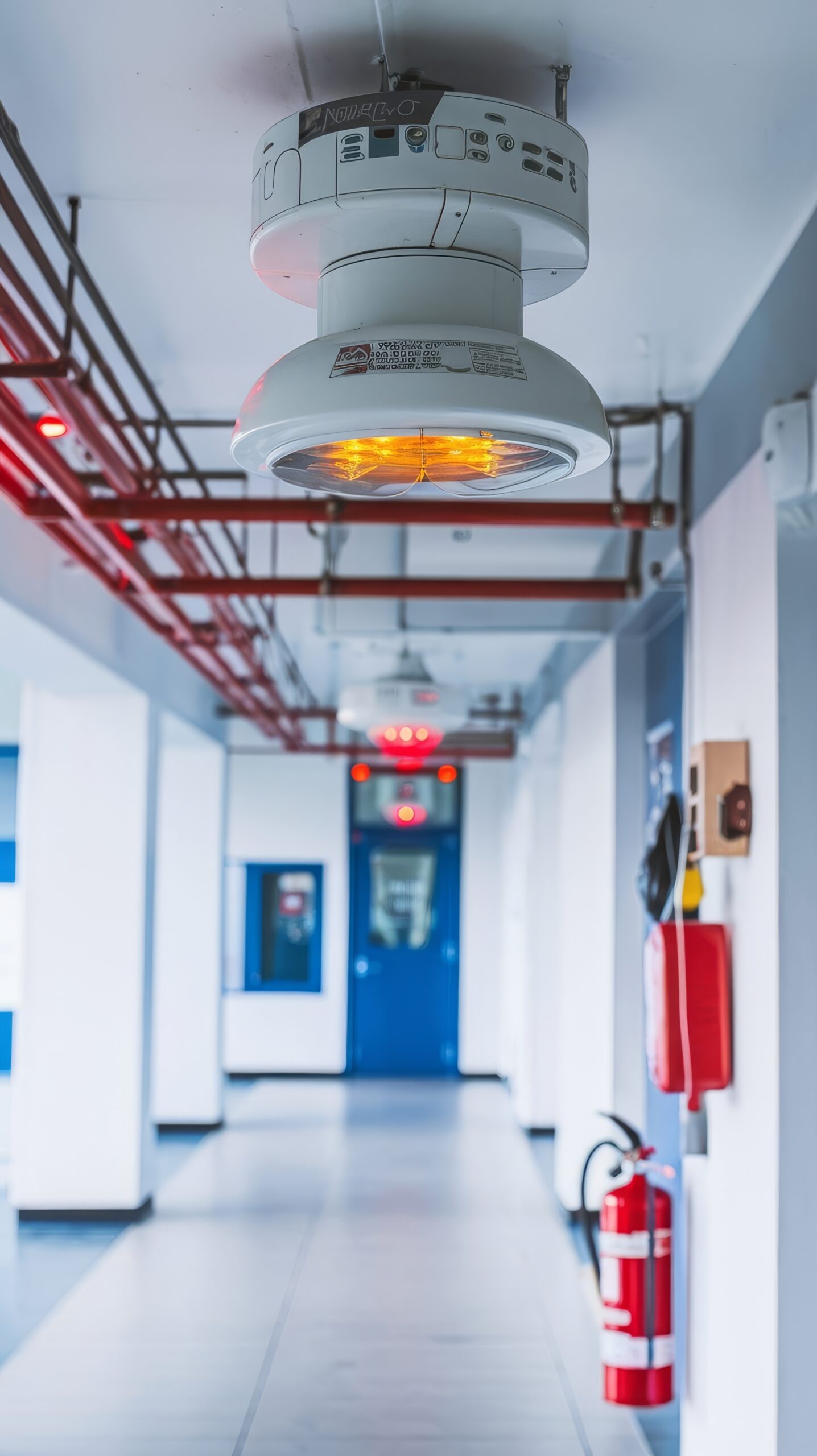
    A smoke detector can remain connected and report normal communications while its sensing chamber becomes contaminated or its response drifts. Maintenance must therefore look beyond panel connectivity. Sensitivity testing, device diagnostics and environmental history provide evidence that a detector remains within its approved operating range.

    Understand what the system reports

    Addressable detectors may provide a sensitivity value, contamination level or maintenance alert. The meaning of those values is manufacturer-specific and must be interpreted with the approved documentation. A percentage or bar graph should not be converted into a pass decision without knowing the reference range and compensation method.

    Some devices automatically compensate for gradual contamination. Compensation can preserve performance for a period, but it is not unlimited and should not be treated as a substitute for cleaning or replacement. Record when the device approaches a maintenance threshold and whether the panel reports that state to operators.

    Test within an approved maintenance program

    Use methods permitted by the applicable code, authority and manufacturer. Functional aerosol testing confirms that smoke can enter the chamber and generate an alarm, while sensitivity testing evaluates the response threshold. Those are related but different questions, so one result should not be used to claim that both were tested.

    Coordinate impairment controls before testing. Notify monitoring parties, protect occupants and restore all disabled outputs after the work. The record should identify the detector, location, method, result, tester, equipment and any corrective action.

    Investigate the environmental cause

    Repeated contamination may indicate dust, construction activity, steam, aerosols, insects or unsuitable air movement. Cleaning the detector without addressing the environment can produce a cycle of nuisance alarms and early failure. Compare maintenance history across nearby devices to identify a local pattern.

    Confirm that detector type and placement remain suitable after room-use changes. A space converted into a workshop, kitchen or high-airflow area may need a design review rather than repeated adjustment. Settings should not be widened simply to silence alarms unless the change is engineered, approved and documented.

    Use trends to plan replacement

    Track devices that repeatedly approach contamination limits, fail sensitivity checks or require frequent cleaning. Trending supports risk-based replacement and helps identify batches exposed to similar conditions. It also distinguishes a single defective device from a broader environmental or design problem.

    Close maintenance by verifying normal panel state, remote annunciation, monitoring communication and updated records. Smoke-detector assurance supports the wider Fire & Safety program by proving that connected devices remain capable of performing their detection function, not merely responding on the network.

    Maintenance analytics should support, not replace, required inspection and testing. Assign responsibility for reviewing contamination trends and overdue work orders, and ensure technicians can trace every device result to its physical location. Any detector removed for service should remain controlled so that an untested device is not returned to the wrong address.
    Reference sources

  • Fire Alarm Loop Fault Isolation and Network Survivability

    Fire Alarm Loop Fault Isolation and Network Survivability

    A fire alarm system may appear normal at the control unit while a single cable fault threatens a large part of the detection or notification path. Loop isolators, redundant communications and supervised circuits are intended to limit that impact, but their value depends on design, placement and testing. Acceptance should prove what remains operational after realistic faults.

    Map the intended fault boundaries

    Start with drawings that show signaling-line circuits, notification circuits, isolators, network nodes, power supplies and interfaces. Identify which devices are expected to remain available after an open circuit, short circuit or node loss. The drawing should match the installed field route, not only the tender design.

    Fault isolation is affected by physical topology. Devices on both sides of an isolator may not fail in the way an operator expects if the cable route, address sequence or return path changed during construction. Record fire compartments, risers and critical functions so the test can assess consequence as well as device count.

    Test faults under controlled conditions

    Introduce approved test faults one at a time using a documented method that protects people and equipment. Confirm the control unit identifies the correct circuit or segment, annunciators receive the condition and unaffected devices continue to operate. Measure how long isolation and restoration take and whether repeated faults produce additional loss.

    An open circuit, short circuit and network communication failure can have different effects. Test representative locations, including boundaries near isolators and remote power supplies. Where a fault could disable a safety function, coordinate compensating measures and restore the system immediately after the evidence is collected.

    Verify interfaces and degraded operation

    Fire alarm systems often control doors, smoke control, elevators, suppression interfaces and monitoring connections. A field loop may retain detectors while losing an interface module that supports another life-safety action. The acceptance matrix should therefore verify required cause-and-effect behavior in the degraded state.

    Confirm that off-site monitoring receives fault and restoration events with correct timestamps. Networked panels should maintain required indications when a peer node or communications link is unavailable. Cybersecurity controls must not block supervised traffic, while maintenance access should remain authenticated and logged.

    Preserve evidence for maintenance

    Close the test with updated drawings, device lists, software versions, fault results and unresolved limitations. Operators need plain-language information about which area is affected by a reported fault and what temporary action is required. A generic trouble message without location or consequence is difficult to manage safely.

    Repeat selected tests after rewiring, expansion, firmware changes or unexplained communication faults. Fire network survivability supports the wider Fire & Safety program by making single-fault behavior visible before an emergency exposes it.

    Coordinate testing with the authority having jurisdiction and the site’s impairment procedure where required. Notify affected occupants and monitoring parties before the exercise, then confirm that normal supervision has been fully restored.

    Reference sources

  • UL FSRI Updates Evidence-Based Structural Firefighting Course

    UL FSRI Updates Evidence-Based Structural Firefighting Course

    UL’s Fire Safety Research Institute has updated its Evidence-Based Structural Firefighting course to connect current fire-dynamics research with operational decision-making. The free online course was updated on September 22 and is designed for both firefighters and personnel responsible for training, policy and procedural consistency.

    New search-and-rescue and hazard content

    FSRI says the revision adds lessons built around 12 tactical considerations from its search-and-rescue research. It also expands guidance on coordinating search, rescue, suppression and ventilation before, during and after fire control. Additional material addresses implementation of NFPA 1700 guidance and emerging hazards including photovoltaic systems and battery fires.

    The course page lists 151 minutes of instruction covering fire science, construction, heat transfer and personal protective equipment, suppression, ventilation, search and rescue, and implementation. It includes a final assessment and certificate of completion. The program is educational guidance rather than a universal incident playbook; departments still need to adapt tactics to staffing, construction, water supply, local procedures and incident conditions.

    From research to operating guidance

    The practical challenge is translating fire research into repeatable training and standard operating guidance without treating one tactic as appropriate for every structure. FSRI’s accompanying fireground playbook is intended to help departments organize evidence-based considerations for their own operations. SectechMedia follows related developments in its Fire & Safety channel.

    Sources

  • Power Resilience and Battery Autonomy for Electronic Security Systems

    Power Resilience and Battery Autonomy for Electronic Security Systems

    Electronic security systems depend on power at cameras, controllers, locks, servers, network switches, communications links and operator workstations. A central uninterruptible power supply may keep the server running while field devices fail. Power resilience therefore begins with the complete operational path, not a single battery specification.

    Define the required security state

    The design team should decide what must remain operational during an outage and for how long. The answer may differ by function. Perimeter detection might need continuous coverage, while selected cameras can move to a reduced frame rate. Access-controlled doors may need to follow life-safety release rules while controllers and event logging remain powered.

    Document the protected loads, acceptable degradation and recovery priorities. Include supporting equipment such as PoE switches, wireless bridges, time servers and monitoring gateways. A device that has power but no network path may still be operationally unavailable.

    Calculate with measured loads and aging

    Battery autonomy should be based on realistic load measurements, conversion losses, temperature and expected aging. Nameplate maximums can overstate normal demand, while a snapshot taken during quiet operation can miss heaters, illuminators, charging or peak lock activity. Use a conservative design method and record the assumptions.

    Battery chemistry, enclosure ventilation and maintenance requirements affect the installation. Capacity normally declines over time, so a system that barely passes at handover may fail before the next planned replacement. Distributed field supplies also need identification and service access.

    Coordinate UPS, generator and network recovery

    Where a generator is available, the battery must bridge startup and transfer without dropping critical loads. Test actual transfer behavior, not only the calculated interval. Some devices reboot after a short disturbance even when average voltage appears acceptable. Network equipment and servers may recover in the wrong sequence, leaving cameras or controllers disconnected.

    A recovery plan should define how services restart, how configuration is preserved and which alarms indicate degraded power. Remote monitoring of battery and supply health is useful only when thresholds are maintained and someone owns the response.

    Test failure modes safely

    Acceptance testing should simulate loss of normal power under controlled conditions. Verify runtime, alarms, transfer, reduced-operation modes and restoration. Inspect event timestamps and confirm that evidence is not lost or corrupted. If the full outage cannot be tested, document the limitation and use component tests with a clear engineering justification.

    Trend results over successive tests rather than recording only pass or fail. A shortening runtime can reveal battery deterioration, increased load or poor environmental conditions before the system falls below its required autonomy.

    Repeat testing after battery replacement, load expansion or major network change. Power resilience is part of industrial safety and monitoring, not a one-time electrical calculation. A reliable design makes the degraded state visible and ensures that restoration does not create a second outage.

    Reference sources

  • Fire Alarm Cause-and-Effect Matrix Testing Explained

    Fire Alarm Cause-and-Effect Matrix Testing Explained

    A fire alarm cause-and-effect matrix defines what the building should do when a specific input or combination of inputs occurs. A smoke detector may initiate evacuation signals, release doors, recall elevators, stop air-handling equipment and notify a monitoring center. Testing the detector alone does not prove that this sequence works.

    What the matrix should contain

    The matrix normally lists initiating events on one axis and required outputs on the other. Inputs may include automatic detectors, manual call points, sprinkler flow, supervisory signals and faults. Outputs can include notification zones, smoke-control commands, fire-door release, elevator interfaces, suppression release logic and messages to external monitoring.

    The document must reflect the approved fire strategy and applicable code requirements. It should identify delays, coincidence logic, dependencies and exceptions. Generic text such as “all systems operate” is not testable. Each expected action needs an observable result and a responsible discipline.

    Prepare an integrated test

    Before testing, confirm that the matrix version matches the installed programming and current building layout. Coordinate fire alarm, mechanical, elevator, door, suppression and monitoring contractors. Notify occupants and authorities as required, establish impairment controls and prevent an unintended emergency response.

    Tests should be planned so that inputs and outputs are observed at their real interfaces. A software indication at the fire panel is not proof that a damper moved or a door released. Where testing a physical action is unsafe or impractical, the alternative method and limitation should be documented.

    Test sequences, failures and recovery

    Verify single inputs, combined inputs and reset behavior. Confirm that priorities are correct when fire and security commands conflict. Door access control, for example, must not prevent the required life-safety release. Check how the system behaves during communication loss, disabled points and power transfer.

    Recovery matters as much as activation. After reset, equipment should return to the intended state without leaving doors, fans or interfaces in an unsafe condition. Operators need a clear indication when a field device requires manual restoration.

    Include negative tests where they can be performed safely. A supervisory input should not start an evacuation sequence unless the approved design calls for it, and an isolated output should generate a visible impairment rather than failing silently.

    Evidence and change control

    Record the test input, expected output, observed result, time, witness and defect. Screenshots can support the record but should not replace signed field observations. Defects must be corrected and the affected sequence retested; broad statements that a problem was “resolved” are insufficient.

    Any later change to fire logic, access control, elevators or smoke control should trigger matrix review. This discipline connects fire detection and automatic protection with the systems it commands. A tested matrix provides evidence that the building responds as a coordinated life-safety system rather than a collection of individually functional components.

    Reference sources

  • Streamlight Launches Hazard-Rated Side-Mounted Firefighter Helmet Light

    Streamlight Launches Hazard-Rated Side-Mounted Firefighter Helmet Light

    Streamlight has introduced the SL-SideSaddle HAZ-LO, a side-mounted helmet light aimed at firefighting and rescue work in locations where equipment may need a hazardous-location rating. International Fire and Safety Journal reported the launch on 21 September.

    Helmet-mounted lighting as safety equipment

    A helmet light keeps both hands available and can illuminate the direction in which the wearer is looking. Side mounting is intended to reduce interference with other helmet components, but fit must be assessed with the complete ensemble, including face protection, communications equipment and breathing apparatus. A light that catches on equipment or changes helmet balance can create a new problem.

    Hazardous-location suitability should be confirmed against the exact certification and operating environment rather than inferred from the product name. Users also need to follow battery, charging and inspection instructions. Damage to seals or housings can invalidate assumptions made at procurement.

    Deployment considerations

    Fire services should test beam pattern, controls and glove usability under realistic visibility conditions. Equipment checks should be incorporated into routine readiness procedures, including battery state and secure attachment. The product sits within a broader emergency and life-safety system in which personal lighting supports, but does not replace, team communications and scene illumination.

    Sources

  • Elevator and Vertical Transportation Security Technology

    Elevator and Vertical Transportation Security Technology

    In most multi-story buildings, the elevator is the fastest way to move between floors — which makes it both a convenience and a security gap. A lobby with a card reader at the front door does little good if anyone who reaches the elevator bank can ride to any floor once inside. Vertical transportation security addresses that gap through a combination of access control integration, fire-service overrides, and monitoring that has to work even when the building’s normal operating logic is suspended during an emergency.

    Destination Dispatch and Floor Restriction

    The most common access-control integration restricts which floors a rider can select, either by requiring a credential at a lobby turnstile before the elevator call is even registered, or by requiring a card or mobile credential to be presented inside the cab before a floor button will respond. Destination-dispatch systems take this further: a rider enters their destination floor at a lobby kiosk rather than inside the cab, and the system assigns them to a specific car and groups passengers heading to similar floors, which both improves traffic efficiency and gives the access-control system a clean record of who requested which floor before they ever board.

    Firefighter’s Service and Fire Recall

    Every access restriction built into an elevator has to yield to fire-service requirements. Under Phase I recall, activating a fire alarm sends all elevators in the affected bank to a designated landing, typically the ground floor, where they park with doors open until firefighters take manual Phase II control using a key switch inside the cab. This recall function overrides any access-control floor restriction in place during normal operation, and life-safety codes require it to work independent of the building’s access-control system in case that system has failed or lost power.

    Shaft and Machine Room Monitoring

    Beyond passenger-facing controls, elevator machine rooms and shaft access points are themselves targets for tampering, since disabling or manipulating elevator controls can create both a safety hazard and a way to bypass floor restrictions elsewhere in the building. Machine room doors are typically included in the building’s access-control and alarm system like any other restricted space, and some buildings add door-position sensors on shaft access doors at each floor to detect unauthorized entry into the shaft itself.

    Cameras in the Cab

    Camera coverage inside elevator cabs presents a narrower field of view and more variable lighting than open building spaces, which has driven demand for cameras designed specifically for cab mounting — typically compact, ceiling- or corner-mounted units with wide-angle lenses and onboard storage or wireless transmission, since cars moving between floors can briefly lose connectivity to a wired network. Video from cab cameras is used both for incident investigation and, increasingly, for analytics that can flag events like a fall or an altercation in the confined space of a moving car.

    Emergency Communication

    Elevator emergency phones remain a code requirement in most jurisdictions, but the technology behind them has moved from a simple two-way phone line to two-way voice communication systems tied into the building’s broader emergency communication and monitoring platform, often with automatic location identification so a monitoring center knows which car and which building a call originates from without the trapped passenger needing to describe their location.

    Reference sources

  • Blue Light Emergency Phone Towers: Campus Communication That Still Works

    Blue Light Emergency Phone Towers: Campus Communication That Still Works

    Blue light emergency phone towers — the tall poles topped with a blue strobe light and a direct-dial emergency phone, common on university campuses, parking structures and transit stations — predate smartphone safety apps by decades, and remain in wide deployment for a specific reason: they don’t depend on the person needing help having a charged, working phone with a signal.

    Why the Technology Persists

    A blue light tower’s core reliability advantage is its independence from the user’s own equipment. A phone with a dead battery, no cellular signal, or a user who is a visitor unfamiliar with a campus’s safety app is still able to reach help through a fixed, clearly marked tower simply by pressing a button, with no account, download, or prior setup required. This makes the technology particularly valuable for visitors, contractors, and anyone in a momentary crisis where fumbling with a smartphone app is a real practical barrier.

    How the Call Routes

    Most modern blue light systems route the call directly to campus police, security dispatch, or a monitored central station, often with the tower’s exact location automatically identified to the responder based on which unit placed the call — removing the need for a caller to describe their location verbally, which is a common source of delay and error in traditional 911 calls, particularly on large or unfamiliar campuses.

    Placement and Visibility Design

    Effective blue light tower placement follows sightline principles similar to other visible-deterrent security infrastructure: towers are positioned so that from any point along a typical pedestrian path, at least one tower is visible, creating both a practical response option and a psychological sense of monitored space. The strobe light itself serves two purposes — helping a person in distress locate the nearest tower, and helping responding officers quickly locate the caller once they arrive on scene.

    Integration With Modern Systems

    Newer blue light tower deployments increasingly integrate with campus video surveillance, automatically directing the nearest camera to the tower’s location when a call is placed, and with mass notification systems, allowing a tower activation to optionally trigger area-wide alerts for incidents that warrant broader awareness rather than just a dispatched response.

    Conclusion

    Blue light emergency towers remain relevant not because they’re more advanced than a smartphone safety app, but because their reliability doesn’t depend on the user’s device, connectivity, or familiarity with an app — a meaningful advantage precisely in the moments when a person is least likely to be in a position to troubleshoot technology. Most campus safety programs today run both systems in parallel, recognizing that different users and different emergencies call for different response paths.

  • Optus Apologizes After Network Outage Disrupts Emergency Calls Across Three Australian States

    Optus Apologizes After Network Outage Disrupts Emergency Calls Across Three Australian States

    Optus, Australia’s second-largest telecommunications carrier, apologized for a 76-minute technical glitch on September 11 that disrupted voice calling — including some emergency-services calls — across Victoria, South Australia, Tasmania and the Northern Territory, Reuters reported.

    The outage follows a 2025 Optus emergency-calling failure that resulted in two deaths, drawing renewed government scrutiny of telecom resilience as a form of critical infrastructure.

    Why it matters: Repeated emergency-calling failures at a major national carrier underscore why telecom networks are increasingly treated as critical infrastructure in their own right, subject to resilience and redundancy requirements comparable to power and water utilities, rather than purely commercial service-quality standards.

    Source: Reuters, September 12, 2026.

  • Duress Alarms and Panic Buttons: Technology Options Explained

    Duress Alarms and Panic Buttons: Technology Options Explained

    A duress alarm, commonly known as a panic button, exists to let someone silently or quickly signal for help during a threatening situation. The concept is simple, but the technology behind it has diversified considerably as organizations look for options that fit different environments, from fixed retail counters to mobile hospital staff moving between patient rooms.

    Fixed Panic Buttons

    The most traditional form is a physical button mounted at a specific location, such as under a reception desk, at a bank teller station, or beside a cash register, wired or wirelessly connected to a monitoring system or directly to local law enforcement. Fixed buttons are simple, reliable and require no action beyond pressing them, but they only protect the person standing at that specific location, which limits their usefulness for staff who move throughout a building.

    Wearable Duress Devices

    Wearable panic devices, worn as a badge, pendant or wristband, extend duress alarm coverage to mobile staff. These devices typically communicate over a building’s Wi-Fi network or a dedicated real-time locating system (RTLS), allowing a monitoring center to see not just that an alarm was triggered but roughly where the wearer is located at the time. This location capability has made wearable duress devices particularly common in healthcare settings, where staff may be assisting a patient anywhere in a facility, and in hospitality, where housekeeping staff often work alone in guest rooms.

    Mobile App-Based Alerts

    Smartphone apps have become a lower-cost alternative or complement to dedicated wearable hardware, letting an employee trigger a duress alert directly from a phone they already carry, often using GPS to share location and sometimes activating audio or video recording automatically when triggered. App-based systems are easier and cheaper to deploy at scale than dedicated wearable hardware, though they depend on the user actively carrying and being able to access their phone during an incident, which is not always possible.

    Integration With Broader Security Systems

    Regardless of form factor, modern duress alarm systems increasingly integrate with video management and access control platforms, so that triggering an alert can automatically pull up live or recorded video from cameras nearest the alarm location, lock down access points in the area, and notify both on-site security staff and, where configured, local law enforcement simultaneously. This integration is intended to compress the time between an alert being triggered and a meaningful response being coordinated, which is generally considered the most important performance factor for any duress system.

    FAQ

    Are silent alarms better than audible panic buttons? It depends on the scenario. Silent alarms are generally preferred when the goal is to avoid escalating a confrontation, such as during a robbery, while audible alarms can be more effective for general emergencies where drawing immediate attention is the priority.

    Do wearable duress devices always include location tracking? Not always continuous tracking, but most wearable systems are designed to report location, either continuously or at the moment an alarm is triggered, since responding effectively to a duress alert usually depends on knowing where the person is.

    Can duress alarms be accidentally triggered? False activations do occur, particularly with wearable devices that can be bumped or pressed unintentionally, which is why many systems include a brief cancellation window or require deliberate multi-second presses to confirm an intentional alert.